TFT Displays for CAN Bus and RS485 Industrial Terminals
Many industrial devices still communicate through CAN bus, RS485, Modbus, and other rugged field interfaces. A compact TFT terminal can make those systems easier to install, diagnose, and operate locally. Instead of relying only on a laptop or remote software, technicians can see status, addresses, alarms, and live values directly on the device, the same local-control value that makes screens useful in robotic arm control.
These terminals are used in motor controllers, sensor gateways, battery systems, utility equipment, building automation, mobile machines, and factory devices. The display does not need to be large, but it must be clear, reliable, and designed around the communication workflow, much like a PLC cabinet door HMI built around local diagnostics.
Why local display still matters
Remote monitoring is useful, but local visibility is often faster during installation and service. A technician standing beside a machine wants to know whether the terminal has power, bus communication, node address, sensor values, and recent errors. A small TFT can answer those questions without opening a laptop.
The display also helps during commissioning. Address setup, baud rate confirmation, termination checks, and device discovery can be shown in plain language. This reduces mistakes and support calls.
Screen size and UI scope
CAN and RS485 terminals often use small to mid-size TFT displays from 2.4 inches to 5 inches. If the terminal only shows status and a few settings, a smaller screen may be enough. If it includes trends, multiple channels, or setup menus, a 4.3-inch or 5-inch display is more comfortable.
The UI should avoid trying to become a full SCADA system. Show the information needed at the device: communication state, values, alarms, configuration, and diagnostics. Larger system visualization belongs elsewhere.
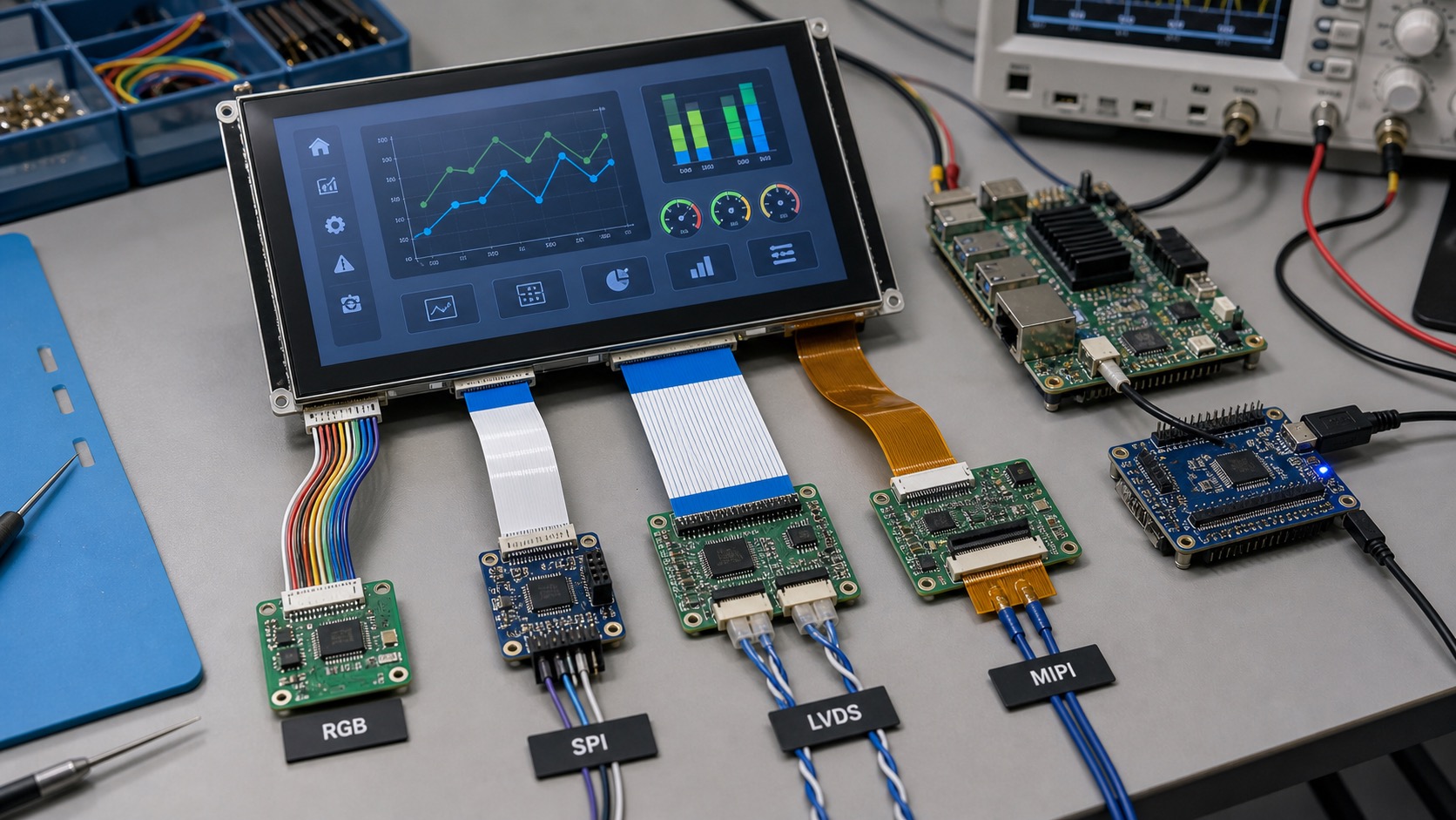
Interface between TFT and controller
The display interface inside the terminal may be SPI, RGB, MIPI, or another local connection, while the external industrial network is CAN or RS485. These are separate decisions. A microcontroller-based terminal may use SPI or RGB. A Linux-based gateway may use MIPI or LVDS.
The processor should have enough resources for the UI and communication stack. If the device handles real-time control, the display task should not interfere with communication timing. Use clear software separation between UI updates and bus communication.
Electrical noise and grounding
CAN and RS485 systems often run in noisy environments with long cables, motors, and power switching. The display and touch panel should not create noise problems or become unstable because of them. Grounding, shielding, and cable routing matter.
If PCAP touch is used, test it while the field bus is active and nearby equipment is switching. False touches or frozen input during electrical noise are field problems, not just lab curiosities.
| Terminal function | Display value |
|---|---|
| Address setup | Shows node ID and baud rate |
| Diagnostics | Shows bus errors and device state |
| Sensor gateway | Shows live values and alarms |
| Motor controller | Shows speed, torque, fault history |
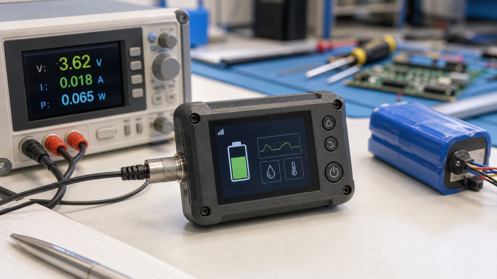
| Battery system | Shows voltage, current, temperature |
| Maintenance | Shows firmware and communication status |
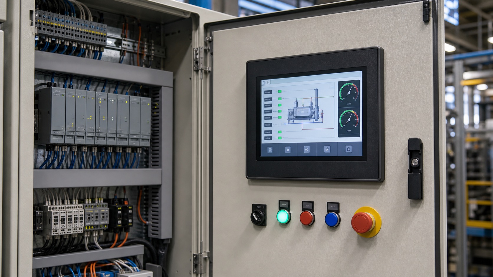
Rugged front design
Terminals may be installed in cabinets, vehicles, outdoor boxes, or machine frames. The display front should match the environment. If the terminal is inside a sealed cabinet, a basic front may be enough. If it is exposed to dust, water, or touch, use cover glass, sealing, and suitable touch technology.
Buttons can be useful. A few physical keys for menu navigation, acknowledge, or back functions can make the terminal easier to use with gloves. Touch is helpful for richer menus but not always required.
Documentation and service
A good terminal display should make troubleshooting easier. Include clear names for communication errors, not only numeric codes. For example, show whether the bus is offline, termination is missing, address conflict is suspected, or packets are being received.
Keep service screens consistent across products. If technicians learn one terminal, they should understand the next. This is a small design habit that improves real-world support.
Commissioning screens
A useful TFT terminal can guide installation step by step. It can show the selected baud rate, node address, termination state, packet count, and last received message time. These details help technicians find wiring or configuration problems without connecting a computer.
For RS485 systems, the display can show whether the device is receiving any traffic and whether responses are timing out. For CAN systems, it can show bus-off state, error counters, or detected node activity. The goal is not to replace advanced tools, but to answer the first troubleshooting questions quickly.
Rugged software behavior
Industrial terminals should handle communication loss gracefully. If the bus is disconnected, the screen should show stale data clearly rather than leaving old values on display. If configuration changes require a restart, the UI should say so.
Local configuration should be protected. A technician may need to change address or baud rate, but accidental changes can take a device offline. Use confirmation screens, access levels, or physical button combinations depending on the risk.
Hardware and enclosure planning
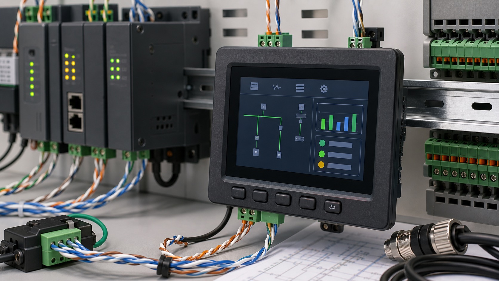
The TFT display, communication transceiver, isolation, and power supply should be designed together. Long field cables can bring surge, noise, and grounding differences. The display front should remain stable even when the communication side is exposed to electrical stress.
If the terminal is installed on DIN rail or inside a small enclosure, heat and cable clearance matter. A bright display in a sealed box can warm the electronics. Good layout keeps connectors accessible and avoids forcing field wiring against the display board.
Details technicians actually use
For this kind of terminal, the useful details are usually plain field details: baud rates, node IDs, termination, stale data, and service screens. These are the terms technicians actually use when they are trying to understand why a device is not talking on the bus.
The terminal should also make firmware updates understandable. If a field device needs updated communication tables or protocol behavior, the display can show update progress and confirm the active firmware version. This is especially useful where devices are serviced by technicians rather than software engineers.
For harsh environments, include a simple screen test page. A technician should be able to confirm touch, backlight, pixels, buttons, and communication status from the terminal itself. This small feature can separate a display issue from a wiring or protocol issue during service.
FAQ
Do CAN or RS485 terminals need large displays?
Not usually. Many terminals work well with compact TFTs, as long as the UI focuses on diagnostics and setup rather than full system visualization.
Can a TFT terminal run on a microcontroller?
Yes. SPI or RGB TFTs are common for MCU-based terminals. The UI should be lightweight and avoid unnecessary animation.
Is touch required?
No. Touch is useful for menus, but physical buttons may be better for gloves, outdoor boxes, or simple diagnostics.
What information should the display show?
Node ID, baud rate, communication status, live values, alarms, firmware version, and recent fault history are practical starting points.