TFT Displays for CNC Machine Controllers
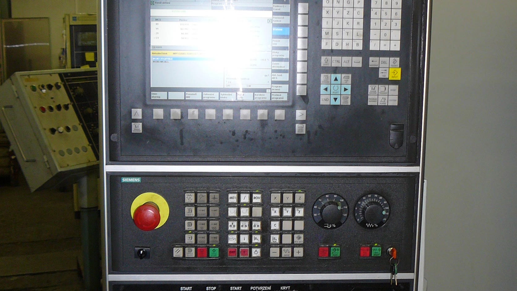
A TFT display for a CNC machine controller has to do three jobs well: present position and program data without ambiguity, survive the electrical and mechanical environment, and remain serviceable long after the original PC platform has changed. A bright screen with a modern touch panel is useful, but it is not the starting point. The starting point is the operator’s work.
During setup, an operator may stand close to the panel and enter offsets. During a production run, the same screen is read from a few steps away. During troubleshooting, a maintenance technician may need alarm history, I/O state, spindle load, and a ladder view. Those are different viewing tasks, and they should drive the screen size, resolution, control layout, and software density.
Start with the screen content, not the diagonal
For a compact machine, a 7-inch panel can handle basic status, jog, tool data, and simple setup pages. A 7-inch industrial TFT is less convincing when the interface must show a program window, axis position, tool offsets, spindle data, and alarm details at the same time. Ten or 12 inches is usually easier to arrange without shrinking text.
Resolution is equally practical. A 1024x600 panel may be enough for a dedicated machine UI. A 1280x800 or 1920x1080 panel gives more room for dense diagnostics, but it also increases framebuffer bandwidth and encourages software teams to add small controls. More pixels do not fix a crowded information hierarchy.
| CNC screen task | Useful display characteristic | Design check |
|---|---|---|
| Production status | Large values and clear machine state | Read from normal standing distance |
| Offset entry | Accurate touch or physical keys | Test with coolant-wet or gloved hands |
| Program review | Stable text rendering and contrast | Check line length and selected-line visibility |
| Alarm diagnosis | Persistent alarm banner and history | Do not hide the first-out condition |
| Maintenance | Dense I/O and trend pages | Keep these separate from operator pages |
The panel should also retain physical controls for actions that benefit from tactile confirmation. Emergency stop, cycle start, feed hold, mode selection, and a manual pulse generator should not be moved onto a touchscreen simply to make the front panel look cleaner. The current ISO 13849-1 framework covers safety-related parts of machine control systems; the HMI must be designed around the machine’s risk assessment, not treated as the safety function by default.
Brightness and viewing angle on a machine shop floor
Machine shops are optically awkward. Overhead LED fixtures reflect from cover glass, enclosure doors, and wet metal. The screen may be mounted above eye level or off to one side. A nominal brightness around 500 to 700 nits is a sensible indoor starting range, but anti-glare treatment and viewing angle often matter more than another 200 nits.
An IPS-type TFT is generally easier to read off-axis than a narrow-view TN panel. That matters when two people are looking at the same alarm or when the panel is mounted on a swing arm. If the front uses a thick protective lens, evaluate the finished stack. The LCD data sheet does not include reflection from the touch sensor, adhesive, cover glass, and air gap.
Optical bonding can improve contrast and mechanical rigidity, although it makes field replacement more expensive. The decision process is covered in our optical bonding guide. For many indoor CNC panels, good anti-glare glass and a controlled air gap are adequate. For open machines with heavy vibration or coolant exposure, bonding becomes easier to justify.
Touch, keys, and dirty hands
Projected capacitive touch works well on sealed modern panels, but CNC operation is not a clean smartphone use case. Coolant film, chips, gloves, grounded metal, and electrical noise all affect the touch system. Tune the controller with the final cover glass and bezel installed. A touch panel tested loose on a bench is not a finished design.
Large touch targets help, especially for jog and setup pages. Destructive actions need an intentional sequence: select, review, confirm. Do not place “delete program” beside “open program” with identical styling. For repetitive numeric entry, a physical keypad can still be faster and more reliable than an on-screen keyboard.
If gloves vary by customer, specify the actual glove rather than writing “glove operation” on the requirement sheet. A thin nitrile glove and an oil-soaked work glove are not the same test load. The same applies to coolant. Use the fluids found on the target machine, including cleaning products used by maintenance.
EMC is usually a system problem
A CNC cabinet contains servo drives, spindle drives, contactors, switching supplies, and long motor cables. The display may be electrically quiet while the assembled HMI is not. Grounding, cable routing, connector shields, and power quality should be reviewed together.
LVDS and eDP are common for larger panels. Keep the display cable away from drive outputs and avoid routing it through a door hinge without strain relief. Bond cable shields as intended by the system design; an unplanned pigtail or floating metal bezel can undo a good interface choice. IEC 60204-1 applies to the electrical equipment of machines and includes EMC and protective bonding considerations; the IEC overview is a useful starting reference.
When a panel resets only during spindle acceleration, replacing the LCD is rarely the first sensible move. Record the HMI supply at the connector, review common-mode paths, and test with the production cable harness. Our common TFT failure modes guide gives a practical way to separate display faults from system faults.
Mechanical mounting and service access
The display frame needs even support. Twisting a module into a slightly distorted door can create light leakage, touch drift, or localized pressure marks. Use a controlled gasket compression and avoid hard points directly against the LCD frame.
Service access deserves an early drawing review. A replacement should not require removal of the entire operator arm. Leave space for the display connector, backlight cable, touch controller, and retaining hardware. Label the cable orientation. If two similar connectors can be swapped, assume that eventually they will be.
For long-life machines, capture more than the supplier part number. Record active area, outline, mounting pattern, interface, timing, voltage, backlight drive, touch protocol, brightness, and viewing direction. That package makes a future second-source or controller update possible.
A practical qualification plan
Bench testing is necessary, but machine testing catches the expensive failures.
| Test | What to look for |
|---|---|
| Cold and hot start | Correct boot, readable contrast, no delayed backlight fault |
| Spindle/servo operation | No image noise, reset, false touch, or communication loss |
| Door and arm movement | No cable pull, intermittent image, or connector movement |
| Coolant and cleaning exposure | No coating damage, edge ingress, or stuck touch |
| Glove operation | Reliable intended touches and rejection of unintended contact |
| Power interruption | Predictable restart without corrupted settings |
| Long run | Stable brightness, temperature, and touch behavior |
Run the display with the real CNC computer, production cable lengths, final cabinet grounding, and representative machine cycles. A generic 24-hour image loop is not enough. The broader sequence in our industrial TFT validation checklist can be adapted to the machine program.
Questions engineers ask early
What screen size works best for a CNC controller?
Seven inches can support a compact, single-purpose controller. Ten to 12 inches is more comfortable when program, position, tool, alarm, and diagnostic information must share the screen. Choose from the busiest real page, not the home page.
Can a touchscreen replace the CNC panel keys?
Not completely. Touch is useful for navigation, setup, and diagnostics. Emergency stop, cycle controls, mode selection, and other risk-related or frequently used actions may require physical controls based on the machine design and risk assessment.
Bottom line
The best CNC controller display is not necessarily the largest or highest-resolution option. It is the panel that an operator can read quickly, a maintenance technician can diagnose, and a machine builder can replace years later. Choose the display after the workflows are known, keep tactile controls where they matter, and validate the complete electrical and mechanical assembly under a running machine.
Engineering references and image credit
- IEC 60204-1: Safety of machinery — Electrical equipment of machines
- ISO 13849-1:2023 — Safety-related parts of control systems
- ISA-101 series for human-machine interfaces
Hero photograph: Pavel Ševela / Wikimedia Commons, licensed under CC BY-SA 3.0. This cropped and resized copy remains available under the same license. The photograph is illustrative; no manufacturer endorsement or affiliation is implied.
.jpg)