Custom TFT FPC Design: Pinouts, Length, and Connector Choices
A custom TFT FPC can solve a difficult connector location and create a new reliability problem if it is treated as a piece of flexible wire. Its geometry, contact system, return paths, and installed bends need to be designed together.
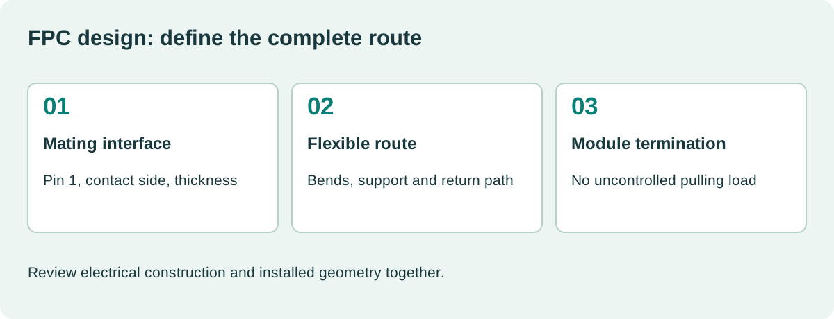
Begin with the complete route from the LCD to the host. Identify which portions remain stationary, which move during assembly, and which move throughout service. A cable that bends once behind a fixed lens has different requirements from a cable crossing a cabinet hinge.
Freeze the electrical definition first
Create a pin-by-pin table that identifies signal names, direction, voltage domain, grounds, power rails, and reserved pins. Define pin 1 in both mating views. Add a clear contact-side drawing rather than relying on a photograph of the copper fingers.
Do not copy a familiar connector pinout onto a new panel without checking the module specification. A physically compatible connector can carry incompatible voltages or map the same differential pair differently.
| Required definition | Why it matters |
|---|---|
| Pin numbering in mating view | Prevents mirrored cable and PCB layouts |
| Contact side and insertion direction | Establishes which conductors touch the connector |
| Finished insertion thickness | Matches the connector’s clamping system |
| Copper and stack construction | Supports current, flexing, and signal requirements |
| Stiffener geometry | Controls insertion and local strain |
| Reserved and test pins | Avoids undocumented production assumptions |
Bring the resulting table into the custom industrial display specification. That keeps electrical customization tied to the module and assembly revision being purchased.
Select the actual mating connector
Pitch and circuit count are only the beginning. Check contact position, locking mechanism, permitted cable thickness, exposed-contact length, and the space needed to actuate the latch.
Molex’s FFC/FPC connector range illustrates the variety of contact and actuator arrangements. Confirm the exact part drawing and application guidance for the selected connector.
The PCB footprint must preserve cable access after surrounding components are installed. A low-profile connector can save height but leave little room to release the latch. Check the assembly tool or finger path in the enclosure model.
Include expected mating cycles in the review. A connector chosen for factory assembly may not suit frequent field replacement.
Separate static and dynamic bends
Ask the FPC manufacturer for bend guidance based on the actual layer stack, copper, thickness, and required cycles. A generic “minimum bend radius” copied from another cable is not enough.
Avoid locating an installed bend directly at the connector contact transition or a bonded module termination. Add support so handling force does not pull on the LCD’s attachment region.
A hinge route needs controlled slack and a defined moving geometry. A longer free loop is not automatically safer if it rubs against metal or repeatedly folds at the same sharp edge. Inspect the route throughout travel.
The TFT mechanical drawing review should include the cable’s installed envelope and the assembly sequence, not only its flat outline.
Treat high-speed pairs as a channel
For LVDS, DSI, or other high-speed links, define the required impedance and routing rules with the host and panel requirements in view. Include the FPC stack, connector transitions, return paths, and any extension board.
Do not assume a differential pair is immune to a poor reference path. A connector break in grounding, excessive pair mismatch, or a sharp stack change can reduce margin.
Length limits belong to the actual transmitter, receiver, cable, connectors, and environment. There is no universal extension length that every MIPI or LVDS panel supports. Review LVDS and MIPI display integration before deciding where a bridge or controller should sit.
Preserve pair identity through the drawings. If the design intentionally swaps polarity or lane assignments, document whether the hardware supports that mapping and where it is corrected.
Size power paths from load and temperature
Estimate rail current, conductor resistance, connector current capability, and voltage drop. Include the ground return. Backlight power can be substantially different from logic power, so treat those paths individually.
As a simple electrical example, 0.4 A through a complete supply-and-return path of 0.5 ohm produces a 0.2 V drop and 0.08 W of loss. Those are calculations, not acceptable limits for a particular FPC.
Check startup current and fault conditions as well as steady operation. Measure voltage at the panel connector under the actual load. A regulator reading on the host board can hide a marginal cable path.
The cable supplier should confirm conductor and thermal capability for the installed environment. Do not infer it solely from trace width without considering construction and enclosure conditions.
Use prototypes to test the route
Evaluate prototype cables in the finished assembly before ordering production tooling. Compare short, straight bench behavior with the intended bends, clamps, and nearby noise sources.
| Prototype check | Evidence to retain |
|---|---|
| Continuity and pinout | Test report tied to cable revision |
| Connector fit | Insertion, locking, and withdrawal observations |
| Loaded voltage drop | Current, temperature, and endpoint measurements |
| Image stability | Worst-case mode and host workload |
| Motion, if applicable | Route, cycle count, and failure criteria |
| Assembly handling | Damage inspection after realistic installation |
| EMC-related behavior | Cable placement and complete test configuration |
For signal-integrity issues, use suitable probes and measurement methods. A test lead that loads a high-speed pair can create the problem being investigated.
Define production inspection and change control
The released cable package should include the electrical table, dimensioned drawing, stack construction, material requirements, connector compatibility, markings, and inspection criteria.
Require the supplier to identify changes to copper, stiffener, adhesive, plating, and manufacturing source where they affect the agreed performance. “Same outline” is not evidence of equivalent flex life or impedance.
Link cable identity to the incoming lot. If a display develops intermittent behavior after assembly, traceability makes it possible to compare the affected cable revision with the approved one.
A display incoming inspection plan can include the cable checks that matter without turning routine receiving inspection into an improvised qualification test.
What if a longer FPC fixes assembly access?
Review the electrical and mechanical consequences before approving it. Extra length can improve connector access while adding voltage drop, coupling, or uncontrolled movement. Evaluate the changed route with the same operating mode and environmental assumptions.
A successful custom FPC has a boring production history: it inserts predictably, stays inside electrical limits, survives the intended handling, and can be replaced without guesswork. Achieving that requires a controlled interface definition and a tested route, not simply a cable drawing with a new length.
A practical handover detail
Make assembly mistakes difficult to repeat. Put readable orientation marks on both ends where space allows, and use distinct identifiers when similar cables are not interchangeable. The work instruction should show the cable seated before the latch closes, the permitted gripping region, and the final routing. If the cable must be replaced in service, test the procedure with the enclosure installed as it will be in the field. Access available on a loose prototype may disappear behind a machine guard.
Sources and image credit
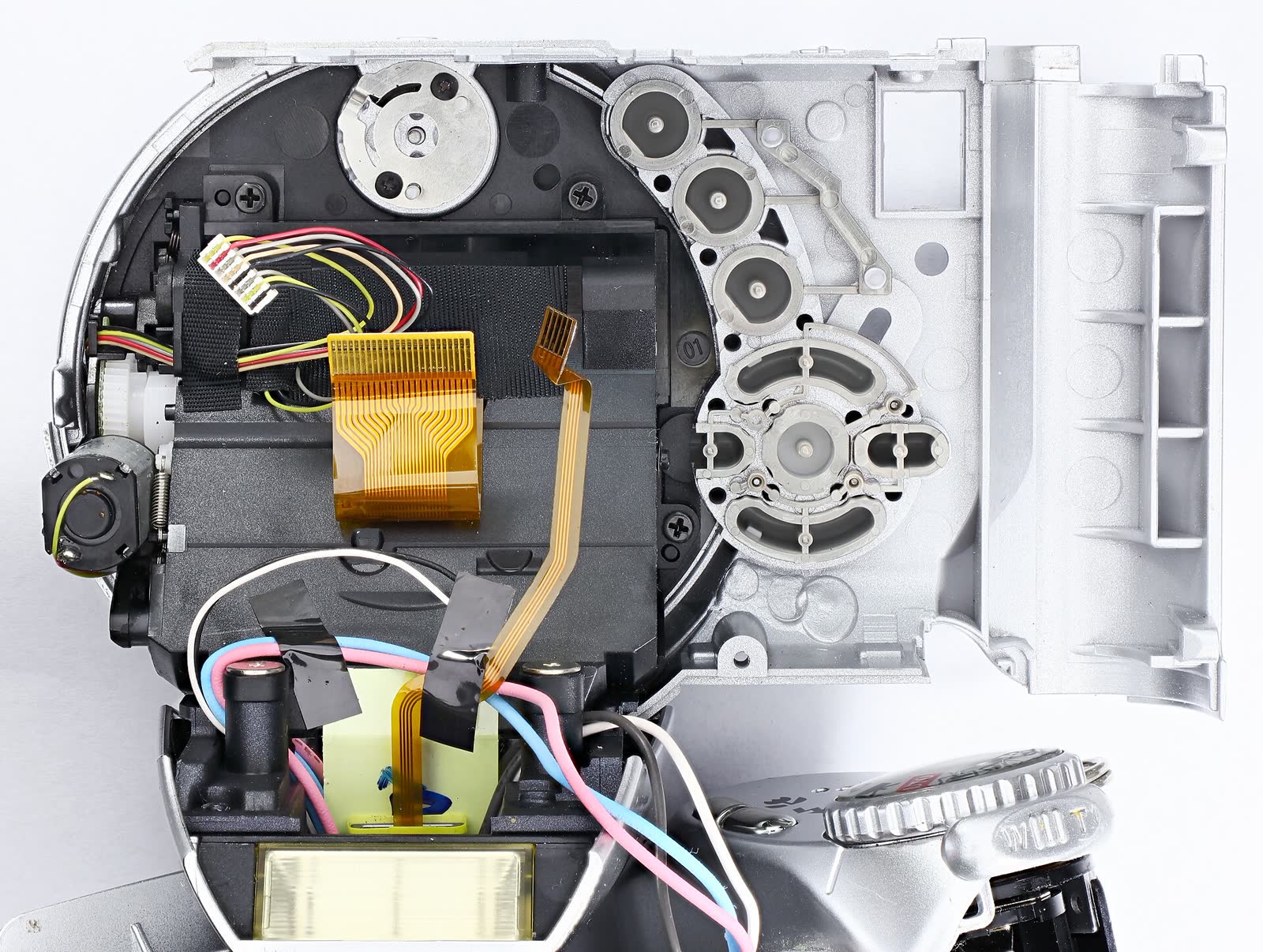
Primary technical references are linked beside the relevant claims. Numerical examples are calculations under the stated assumptions. The original diagram explains the design method; neither it nor the photograph represents a qualification test performed by this site.
Hero photograph: Mister rf, CC BY-SA 4.0. Resized and JPEG-compressed. This adapted photograph remains under the linked ShareAlike license.