Embedded TFT Powers On but Shows a Black Screen: A Debugging Guide
A lit power LED tells you almost nothing about the display path. The host may have booted while the LCD is held in reset, the backlight enable may be low, or the display controller may be scanning a buffer filled with zeros.
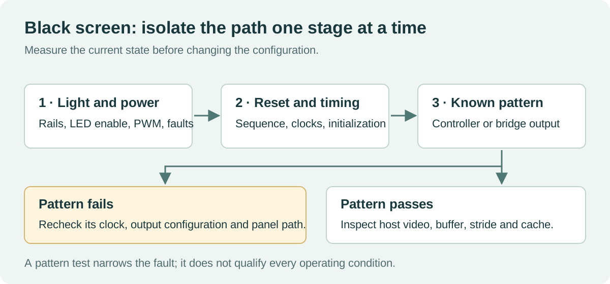
For TFT black screen troubleshooting, divide the problem into observable stages: light, panel power, initialization, transport, and pixel data. Get one piece of evidence at each stage before changing settings. Otherwise, a new initialization sequence can hide a loose connector and leave the original fault waiting for the next reboot.
The procedure below is for documented embedded display assemblies. Use the board’s safe test points and rated probes. Disconnect power before reseating an FPC; a connector that is easy to reach is not necessarily designed for hot plugging.
Record what “black” actually means
Inspect the panel in moderate ambient light and in a darker setting. Look from several angles. An illuminated black image, an unlit backlight, and a panel with no valid drive can appear similar from the front.
| Observation | First branch to investigate | What it does not prove |
|---|---|---|
| No visible glow | Backlight supply, enable, PWM, driver fault | The pixel path is also broken |
| Faint image visible with oblique illumination | Backlight path | Every panel will respond to this test |
| Uniform glow with no picture | Panel initialization, timing, image data | The LCD itself is defective |
| Brief image, then black | Sequence, host handoff, blanking, power dip | The cable is necessarily good |
| Works after a warm restart only | Reset and rail discharge behavior | Longer arbitrary delays are the final fix |
| Pattern works, application does not | Upstream data or rendering path | All operating modes are qualified |
Take a short startup video and save serial logs with the same power cycle. Note the board revision, panel label, cable revision, and software build. Reproducibility is more useful than a collection of unrelated register changes.
Check the connector before the graphics stack
Compare the panel’s pinout with the schematic and cable drawing. Confirm contact orientation, pin numbering, supply voltage, ground positions, and connector latch engagement. Similar-looking FPC connectors can have different contact sides or assignments.
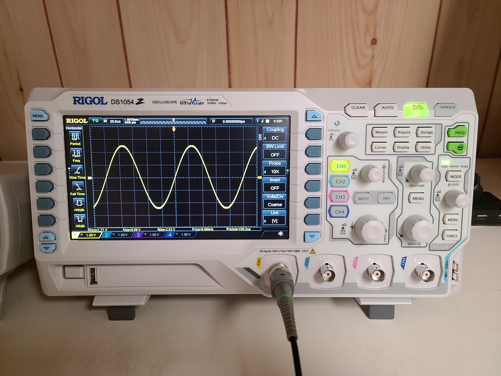
Measure rails at the panel connector, not only at the regulator. A resistive connection can pass a continuity test and still drop voltage under load. Capture startup with an oscilloscope if the failure is transient; a multimeter can miss a short dip.
Do not assume that touch enumeration proves the LCD is powered. Touch and display functions often have separate supplies and data paths. Likewise, a responsive host application does not prove that its display engine is active.
For faults that appear after assembly or cable movement, the wider industrial TFT failure analysis process helps identify mounting pressure, harness stress, and environmental contributions.
Treat backlight and pixel drive as separate systems
Check the LED driver’s input supply, enable level, PWM input, and fault status against its data sheet. A running PWM signal may still command negligible brightness if its polarity or duty-cycle interpretation is wrong. Some drivers also support an independent current-setting register.
Do not connect LED strings directly to a voltage source to “see whether they work.” Use the specified current-regulated driver and keep within the documented limits. An open or shorted string can make a driver enter protection even when its input supply is correct.
If the panel is illuminated, move on. Increasing brightness cannot correct missing pixel data. The LCD backlight control requirements should be checked separately from the display interface configuration.
Measure reset and power sequencing
Use the exact panel and bridge specifications. There is no universal sequence of delays that works for every TFT. Record rail ramp, reset assertion and release, clock presence, initialization commands, valid video, and backlight enable on a shared timeline where possible.
A common integration trap is that a warm software restart leaves a bridge or panel powered. The resulting state differs from a cold boot. Test both, plus a short power interruption that does not fully discharge every rail. Check for unintended powering through signal pins when a supply is off.
If changing a delay makes the screen work, measure the event that the delay is protecting. It may be waiting for a rail to settle, a PLL to lock, or a command to finish. Convert the observation into a documented sequence rather than leaving an unexplained pause in the code.
Use a pattern generator to split the path
Some bridges and display controllers can generate a built-in test pattern. That can separate panel output and timing from host video generation. It is useful only when its clock and configuration requirements are understood.
For a concrete example, the TI SN65DSI83 data sheet documents a DSI-to-LVDS bridge with test-pattern support. TI’s bridge debugging material discusses checking timing, register configuration, and the panel requirements together. Apply those details to that device family, not blindly to another bridge.
If the internal pattern is correct, save the working register dump. Disable the pattern and restore the host stream without changing the downstream panel configuration. If the image now disappears, investigate the upstream path first. A passing pattern still does not validate every resolution, temperature, or cable length.
Check the interface according to its type
| Interface | Configuration to verify | Useful evidence |
|---|---|---|
| Parallel RGB | Pixel clock edge, DE, sync polarity, porch values, bus width | Measured timing and a simple color-bar image |
| LVDS | Lane wiring, bit mapping, clock, single/dual-link configuration | Known-good output pattern and receiver-compatible timing |
| MIPI DSI | Lane count, lane rate, video/command mode, initialization | Host/bridge status and documented DSI sequence |
| SPI or MCU bus | Reset, command/data selection, pixel format, address window | Captured command transaction and a small solid rectangle |
An ordinary logic analyzer is useful for suitable low-speed control buses, but not a substitute for appropriate differential probes and protocol tools on high-speed links. Start with register state and low-speed control evidence before disturbing a marginal high-speed signal with the wrong probe.
For DSI-specific setup, work through the MIPI DSI bring-up checks with the selected panel’s initialization requirements beside you.
Prove that the buffer contains visible pixels
Remove the UI framework temporarily and display a known solid color or test pattern from a verified buffer. Check its address, size, stride, pixel format, visibility settings, and layer alpha. A correctly scanned fully transparent layer can look like a display failure.
On a noncoherent memory system, confirm that DMA can see CPU-written pixels. Inspect cache handling and whether the framebuffer resides in memory accessible to the display engine. A valid CPU pointer is not proof that every bus master can reach the same region.
If a static pattern works but animation fails, log underruns and memory traffic. The embedded display memory bandwidth budget may be the missing constraint. If the screen goes black only when the operating system takes over from the bootloader, compare the two timing and power configurations.
Close the fault with a repeatable test
After finding the cause, restore the production UI and repeat cold starts, warm restarts, and the original failure trigger. Save the failing and corrected configuration, the decisive measurement, and the affected hardware revisions. That small record prevents the next engineer from repeating the same investigation when a panel or firmware revision changes.
Sources and photograph
Manufacturer references are linked in the test-pattern section. The troubleshooting order is a general diagnostic workflow, not a substitute for a particular panel’s electrical specification.
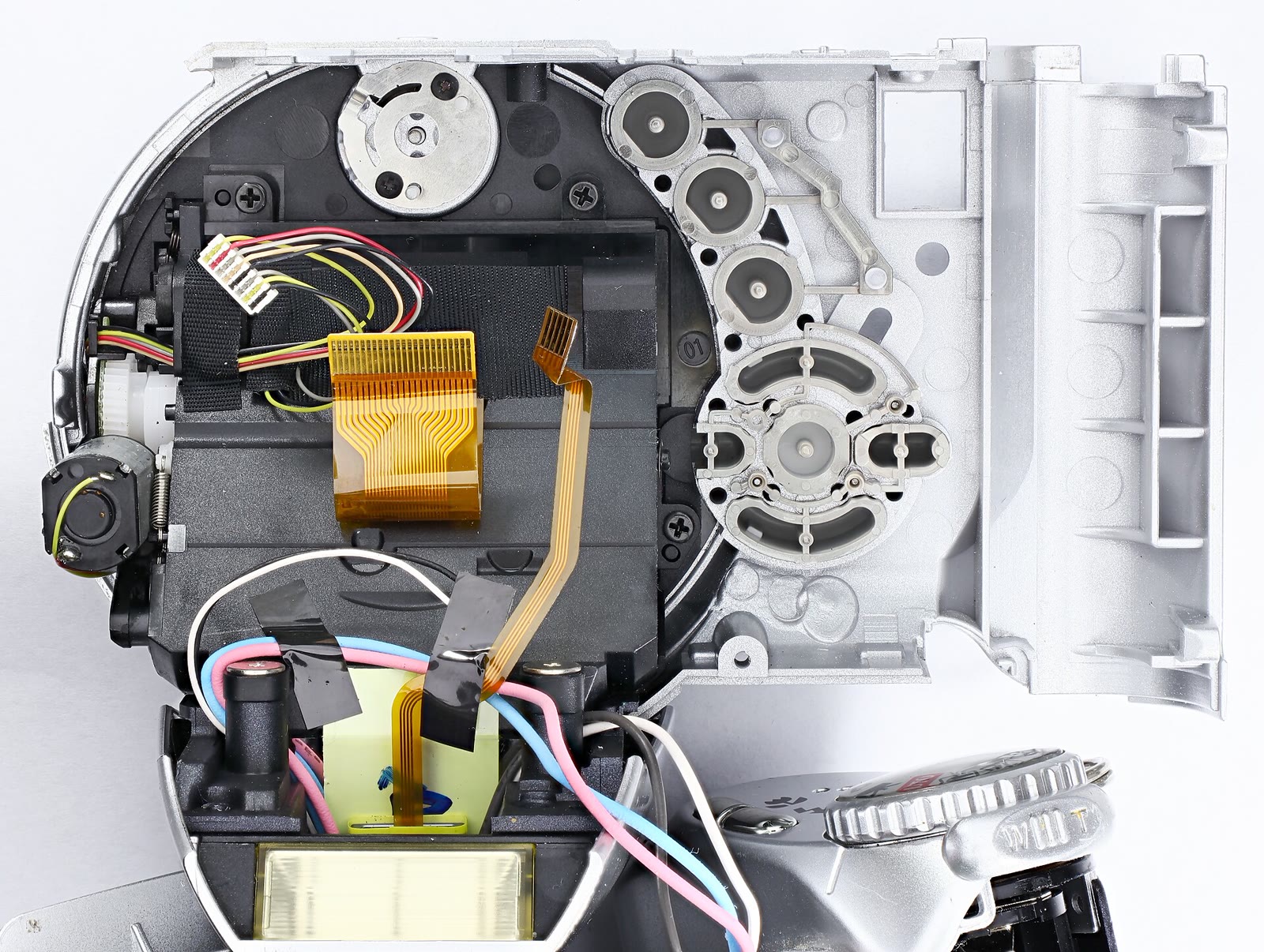
Hero photograph: Mister rf, Minolta DiMAGE Z1 teardown, CC BY-SA 4.0. Resized and JPEG-compressed; the adapted photograph remains under CC BY-SA 4.0. The diagnostic illustration is original.