How Industrial TFT Displays Empower Robotic Arm Control in Modern Factories
Introduction
In the heart of every modern smart factory lies a crucial element: precision control. Whether it’s monitoring the torque of a robotic gripper, visualizing temperature and force sensor data, or fine-tuning movement parameters, real-time visual feedback is key.
This is where an industrial TFT display earns its place. Unlike consumer-grade panels, these displays are built for rugged environments, with higher brightness, longer lifecycle support, and touch behavior that can be tuned for real operators. In a robotic arm cell, even a 4-inch screen can become the local window into status, alarms, jogging, and recovery.
Use Case: Robotic Arm Control Terminal
A mid-sized electronics manufacturing company integrated 4” TFT LCD modules into their robotic workstations. Each robotic arm was responsible for precision soldering tasks under microscopic conditions. Previously, all configuration and monitoring were performed remotely via a desktop PC. This caused:
- Slow manual calibration
- Lack of local feedback during runtime
- Difficulty in on-site diagnostics
To solve these issues, engineers embedded a 4-inch industrial TFT display directly into the control box mounted near each robotic arm.
Why a 4-Inch TFT Display?
| Feature | Benefit in Robotic Application |
|---|---|
| Compact Size | Easily mounts on control boxes or robotic frames |
| 800x480 / 480x272 resolution | High enough for parameter display & graph rendering |
| High Brightness (≥500 nits) | Visible even under overhead factory lighting |
| Capacitive Touch Support (CTP) | Enables gloved hand operation |
| Wide Temperature Support | Operates from -20°C to 70°C reliably |
| Low Power Consumption | Critical for embedded system integration |
The display is paired with a small embedded SBC (like Rockchip PX30 or STM32 MPU) to run a Qt or LVGL-based HMI software.
Display UI Design
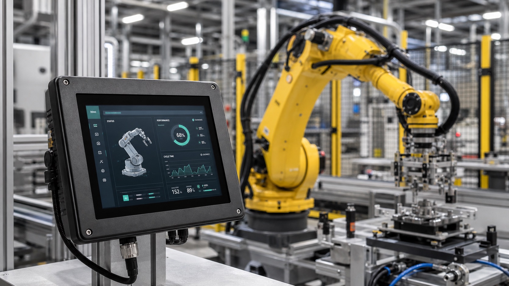
The GUI is minimalistic yet powerful. The screen is divided into 3 major sections:
1. Status Overview Panel
- Live arm position (X, Y, Z axis)
- Current joint torque
- Cycle time counter
- Operation mode (auto/manual/emergency)
2. Sensor Feedback Area
- Thermistor readings from joints
- Real-time force sensor feedback
- Vibration level (filtered from accelerometers)
Color-coded bars and icons allow technicians to quickly spot any abnormal values.
3. Manual Override and Tuning Interface
- Virtual sliders for adjusting speed or torque
- Button pad for jogging movements
- Script upload via USB/OTA
Touch interaction is enhanced with sound haptics and lockout features to avoid accidental presses.
How the Display Enhances Control
The embedded TFT not only shows information but becomes a control interface in itself. Here’s how it changes the game:
- Local Autonomy: Technicians can operate, calibrate, and restart robotic arms without a separate PC.
- Faster Debugging: If a soldering error occurs, the cause (e.g., torque spike) is shown instantly on-screen.
- Operator Empowerment: Clear feedback builds confidence, especially in high-precision operations.
Ruggedization Considerations
For this application, the TFT display is:
- Optically bonded to enhance contrast and block dust/moisture
- Protected with anti-glare AR coating for better visibility
- Placed behind a 4mm hardened glass layer
- Secured with EMI shielding and screw-mounted PCB brackets
This ensures long-term stability even under high-vibration and high-EMI industrial environments.
Software Stack
The embedded SBC runs a customized Linux image (based on Buildroot), with an HMI application developed using:
- LVGL: Lightweight for low-power SoCs
- Qt5: When richer UI effects are needed
- Modbus/RS485: For PLC/robotic controller communication
- MQTT: For sending telemetry to the factory’s central system
The display supports multi-language UI, switchable via the on-screen menu.
Deployment Impact
After rollout to 20 robotic stations, the manufacturer observed:
| Metric | Before TFT Upgrade | After Upgrade |
|---|---|---|
| Mean Time to Calibrate | 15 minutes | 3 minutes |
| Downtime per Day | 1.2 hours | 15 minutes |
| Operator Training Time | 4 hours | 1.5 hours |
| Error Diagnosis Speed | Slow (log files) | Instant (screen alerts) |
These results reinforced the role of embedded displays not just as passive outputs, but as active drivers of productivity.
Broader Applications
This TFT-based interface approach isn’t limited to robotic arms. Similar screen systems are now widely used in:
- CNC machine panels
- AGV/AMR control stations
- Industrial HVAC and pump controllers
- Laboratory automation equipment
- Elevator diagnostics terminals
As screens become cheaper, more reliable, and power-efficient, they are finding their way into edge devices across every factory segment.
Selection Notes for Robotics Teams
When a TFT display is used beside a robotic arm, the first selection filter should be the operator task. A maintenance technician needs alarm history, axis position, jog controls, and calibration pages. A line operator may only need status, recipe selection, and a clear stop or reset flow. These two users should not be forced into the same screen layout.
For robotic cells, readability under factory lighting is usually more important than extreme brightness. A display in the 500 to 800 nit range is often sufficient indoors, but wide viewing angle and anti-glare cover glass can make a bigger difference. If the panel is mounted near welding, inspection lights, or reflective guarding, the team should test glare with the actual enclosure installed.
Touch input also deserves early validation. Many operators wear gloves, and maintenance staff may interact with the screen while holding tools. Large controls, confirmation for risky commands, and a lockout state during automatic motion are practical design choices. The display should never make it easy to jog an axis by accident.
Finally, the HMI should expose enough diagnostic information to reduce dependence on a laptop. Servo fault codes, I/O status, network state, and current recipe should be visible in plain language. That small amount of local transparency can save minutes every time a line stops.
FAQ
What size TFT display works best for robotic arm control?
Small local controllers often use 4-inch to 7-inch displays. Larger cells may use 10.1-inch screens when operators need trend charts, camera views, or more detailed diagnostics.
Should a robotic HMI use touch only?
Touch is useful, but critical motion and emergency functions should follow machine safety requirements. Many systems combine touch interaction with physical emergency stops, enable switches, or keyed access.
Is optical bonding necessary in factory robotics?
It is not always required, but it helps when dust, vibration, cleaning, or strong reflected light are present. It can also make the front stack feel more solid.
Conclusion
The 4-inch industrial TFT display is not just a screen — it’s a window into the heart of smart machinery. By enabling real-time data visualization and control, it transforms robotic arm systems from black-box components into transparent, manageable tools.
In smart factories where every second counts, this level of interaction and feedback is indispensable. As Industry 4.0 pushes for decentralized, intelligent edge nodes, expect these screens to be a central interface in everything from robotic welding to automated inspection.