When to Use an HDMI Controller Board with an Industrial TFT
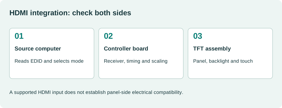
An HDMI controller board can make a bare industrial TFT behave like a monitor, which is useful when the host already provides HDMI. The board still has to match the LCD’s electrical interface, timing, backlight, and power sequence. An HDMI socket on one side does not make every panel on the other side interchangeable.
Use the board when it removes a meaningful integration burden. For a prototype, that may mean connecting a standard computer quickly. For production, the decision also includes startup behavior, firmware control, serviceability, and whether the complete assembly meets the environmental requirements.
Identify what the board actually does
An HDMI receiver, a scaler, a panel bridge, and a complete LCD controller are different building blocks. Some boards accept several input timings and scale them to a fixed panel mode. Others support a narrower path without general scaling.
List every function between the source and LCD. Include the panel interface, LED driver, touch controller, audio path if used, and any separate keypad board. Touch commonly travels over USB or another independent connection rather than through the HDMI video path.
Analog Devices’ ADV7611 receiver documentation is one concrete example of a receiver component. It does not by itself describe a complete panel controller; check which additional functions the proposed board implements.
| Board function | Question for the supplier |
|---|---|
| HDMI reception | Which input timings and signal formats are supported? |
| Scaling | Is native input mapped one-to-one or resampled? |
| Panel output | Which exact timing, voltage, and bit mapping are configured? |
| Backlight | Are current, string arrangement, and dimming compatible? |
| Power management | What happens during source loss and restart? |
| Firmware | Can the approved configuration be identified and controlled? |
Request the configuration for the exact LCD part and revision. “Supports LVDS” is not a complete compatibility statement.
Understand EDID and preferred timing
EDID tells the source what modes the display assembly advertises. The controller board’s stored data may describe a generic monitor rather than the native panel configuration.
Check what the actual host reads. Verify its selected mode after cold boot, reconnect, and operating-system startup. A system can show a correct boot image and later switch to a mode that introduces scaling or fails to display.
The Linux kernel EDID documentation describes the role of display identification and handling of incorrect information. Use the relevant operating-system tools to inspect the delivered data rather than trusting a supplier screenshot.
For a dedicated industrial instrument, specify the intended native mode and what happens if the host proposes another mode. A hidden automatic fallback can produce a usable picture with unexpectedly small text.
Inspect scaling with the actual interface
Display fine lines, a checkerboard, small text, and circles at the intended resolution. A scaler can soften text, alter line widths, or crop edges. Overscan behavior that is tolerable for video is usually inappropriate for an operator interface.
Keep the host’s display scaling and the board’s scaling separate in the investigation. A desktop environment may enlarge UI elements even when the video signal is native. Record both settings.
Our industrial HMI resolution planning guide explains why physical control size must remain part of the review. A crisp image still fails the task if the keypad is too small to operate.
If the instrument contains waveform or camera information, verify that the scaling method preserves what the user needs. Do not infer measurement accuracy from a sharp-looking trace.
Budget power and temperature for the board
The controller adds power consumption and heat behind the panel. Check its supply current during startup, maximum brightness, source reconnection, and normal operation. Include the LED driver if it shares the input supply.
A wide-temperature LCD does not extend the rating of the receiver, scaler, memory, oscillator, connectors, or firmware configuration. Obtain the board’s operating conditions and test the assembled enclosure.
Check the hottest component and the air near the LCD. A board that runs comfortably in open air may become marginal when a sealed front panel limits convection. Cable strain relief and insulation should not block cooling paths.
Use the industrial TFT thermal qualification checklist to connect component checks with enclosure-level tests.
Define the operator experience during signal loss
Some generic boards display a bright “No Signal” box, a vendor logo, or an on-screen menu when video disappears. In a machine or instrument, those behaviors can obscure the intended fault indication or confuse users.
Specify whether the board should blank, retain an image, show a controlled message, or let another system present the fault. Retaining the last image requires a clear stale-state strategy at product level.
Test the source starting before the controller and the controller starting before the source. Include short power interruptions, cable reconnects, host sleep, and a restart while the panel remains powered.
| Event | Behavior to verify |
|---|---|
| Host absent at startup | Predictable indication without indefinite distracting menus |
| HDMI unplugged | Explicit loss state and controlled recovery |
| Host changes mode | Supported result without hidden cropping |
| Brownout | Repeatable restart without corrupted settings |
| Firmware replacement | Approved timing and EDID restored |
| Touch USB reconnect | Correct coordinate mapping and device association |
Do not solve a startup race solely by inserting an unexplained delay. Identify the rail, reset, or handshake condition that needs to become valid.
Make the wiring a production design
An ordinary HDMI cable may be convenient during development but unsuitable for vibration or repeated cabinet-door motion. Review retention, bend radius, strain relief, shielding, and access for replacement.
The panel-side cable is equally important. Confirm pinout, contact orientation, grounding, and backlight wiring. Similar connectors can expose different voltages and should not be treated as interchangeable.
Compare the total integration with a native industrial display interface. A direct host interface can remove a board, while HDMI can simplify host substitution. The better choice depends on the complete system and its service model.
Control firmware and purchasing substitutions
Record board hardware revision, firmware checksum or version, EDID contents, panel configuration, cable revision, and backlight settings. Photograph the approved assembly for identification, but retain configuration files too.
Ask how production changes are notified. A visually identical controller with a different scaler or firmware can change boot delay, unsupported-mode behavior, power draw, or image appearance.
For a fault investigation, retain a known-good host, cable, and controller configuration. The embedded TFT black-screen checks can then isolate the HDMI source, controller output, panel power, and backlight separately.
When is the extra board justified?
It is justified when standard host connectivity, service replacement, or software simplicity outweighs its space, heat, and configuration cost. Make that decision with a tested assembly and controlled firmware, not merely a successful desktop picture. The production deliverable is a documented monitor subsystem that behaves predictably throughout startup, operation, and recovery.
A practical handover detail
For a production trial, retain the source’s selected video mode and the EDID binary alongside the controller firmware identity. Compare them after replacing either board. If the supplier cannot provide a firmware version, agree on another controlled identification method before accepting routine substitutions. A startup photograph cannot reveal whether two boards use different EDID contents or unsupported-mode policies. Those differences often stay hidden until a host operating-system update changes how the preferred mode is selected.
Sources and image credit
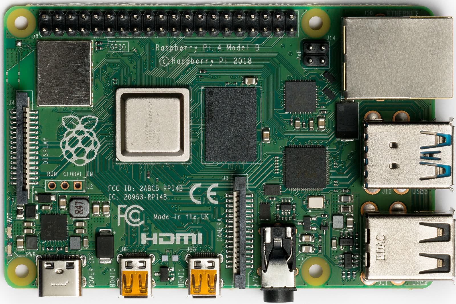
Primary technical references are linked beside the relevant claims. Numerical examples are calculations under the stated assumptions. The original diagram explains the design method; neither it nor the photograph represents a qualification test performed by this site.
Hero photograph: Laserlicht, CC BY-SA 4.0. Resized and JPEG-compressed. This adapted photograph remains under the linked ShareAlike license.