How to Read a TFT LCD Mechanical Drawing
A TFT LCD mechanical drawing is a map of several different objects: the visible image, the glass and frame, the mounting system, and the cable that has to reach the host board. Treating all of those outlines as the same rectangle is a reliable way to lose time at the first enclosure build.
Read the drawing with the actual assembly sequence in mind. Ask where the part locates, what supports it, which surface carries the seal, and how a technician will disconnect it. A dimension can be correct on paper while leaving no room for a hand or connector latch.
Start with revision and projection
Confirm the part number, drawing revision, units, projection convention, and whether the drawing represents a bare LCD or a bonded touch assembly. Record the document’s approval status. A quotation drawing with reference dimensions is not automatically a released manufacturing definition.
Open the front, rear, and side views together. Mark the viewing direction before interpreting connector position. “Connector on the right” becomes ambiguous when one person means the rear view and another means looking through the front glass.
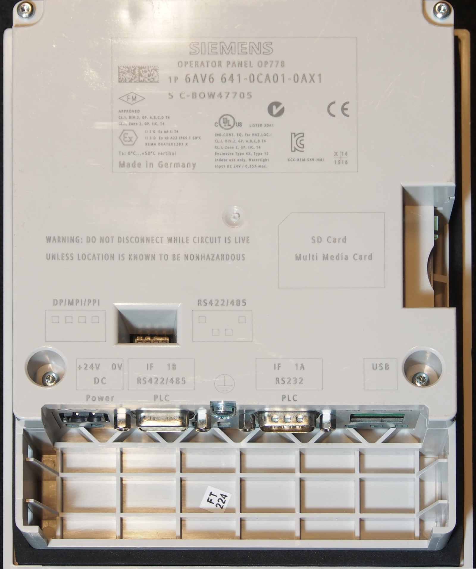
A screen photograph helps identify orientation, but a photograph is not a scale drawing. Use the controlled dimensions for fit decisions and ask the supplier to resolve missing tolerances.
Distinguish active area, viewing area, and outline
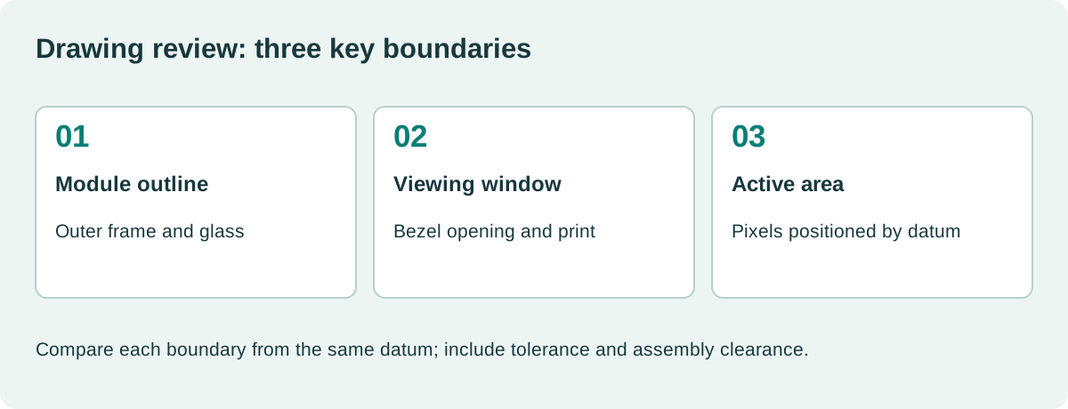
The active area is the pixel image. The viewing area is the unobscured opening through which it is seen. The module outline includes structural material beyond the image. A custom lens may introduce a fourth boundary: the printed window.
| Drawing feature | What it controls | Common integration error |
|---|---|---|
| Active area | Image size and position | Centering the bezel on the module rather than the image |
| Viewing opening | Unobstructed view | Clipping edge pixels with printing or a gasket |
| Module outline | Available enclosure volume | Assuming its center equals the image center |
| Mounting datum | Repeatable location | Referencing cosmetic edges with loose tolerances |
| Maximum thickness | Rear clearance | Ignoring components or adhesive thickness |
| Connector envelope | Cable and latch access | Providing space for the plug but not insertion |
Check how the drawing defines these terms. Suppliers may use abbreviations differently. The important point is to identify the physical boundary behind each dimension rather than guess from its label.
Use an industrial LCD requirements checklist to carry those boundaries into the product specification. Include the final lens and touch configuration, not just the LCD purchase code.
Build the tolerance chain
Suppose an enclosure opening is nominally 155.0 mm wide and the module feature entering it is 154.0 mm. The nominal clearance is 1.0 mm. If the opening can be 0.3 mm smaller and the module 0.4 mm larger, only 0.3 mm total remains in that worst-case dimensional comparison.
That is an illustrative stack, not an adequate clearance recommendation. Position error, coating thickness, assembly skew, thermal expansion, and gasket behavior still need consideration. Total clearance also does not guarantee equal clearance on both sides.
Select the locating datums first, then calculate the dimensions from those datums to the lens window, mounting holes, connector, and supporting frame. Do not add unrelated dimensions from several views without checking their references.
For statistically combined tolerances, confirm the manufacturing assumptions. A root-sum-square calculation should not quietly replace a required worst-case fit check.
Mount the frame without distorting the cell
Identify which surfaces the supplier permits to carry load. A metal flange may be suitable for retention while the nearby glass edge is not. Keep screw heads, clips, adhesive beads, and gasket reactions away from unsupported optical areas.
Control the compression path. If tightening a screw pulls the LCD into a warped door, the assembly can develop pressure marks or light leakage. A drawing review should identify hard stops and support surfaces, not merely screw locations.
Check whether mounting holes are for grounding, location, retention, or several functions. Do not assume all holes can be tightened to the same torque. Request the permitted fastener and tightening method where the module supplier specifies them.
Our industrial display mechanical validation discussion provides the next step after drawing review: verifying the assembled structure through realistic handling and environmental tests.
Follow the cable all the way to its connector
An FPC drawing needs contact-side information, pin numbering, stiffener details, insertion thickness, and a usable mating part number. The cable’s flat outline is not its installed volume once bent.
Molex’s FFC/FPC connector information shows why pitch alone is insufficient: connector families differ in contact arrangement and actuator design. Use the exact connector drawing to verify compatibility.
Leave access to open the latch and withdraw the cable without pulling on bonded regions. Check bend geometry against the FPC manufacturer’s limits. A fold that fits a rendering may be unsuitable for repeated assembly or vibration.
For a detailed electrical and routing review, connect the mechanical package to the custom display FPC pinout definition. The two documents should agree on orientation and revision.
Review the installed assembly and the service state
For a changed cable route, verify the TFT FPC connector and bend design alongside the enclosure drawing rather than extending the cable on geometry alone.
The display may fit after the enclosure is closed but be impossible to install without bending the cable sharply. Model the sequence with fasteners, door hinges, controller boards, and cable clamps present.
| Review state | Question to answer |
|---|---|
| Initial insertion | Can the module enter without contacting glass edges? |
| Cable connection | Is the latch accessible before the board is fixed? |
| Final tightening | Does the load path stop before the LCD is distorted? |
| Door movement | Does cable slack remain controlled through full travel? |
| Replacement | Can the correct part be removed without damaging the seal? |
| Reassembly | Are orientation and compression repeatable? |
Include the gasket’s free and compressed thickness where relevant. The adhesive liner removed during assembly can also affect handling clearance even though it does not remain in the product.
What should a supplier drawing review return?
Return a marked-up drawing with numbered questions, the product-side mating dimensions, and the required configuration. Ask whether each unclear dimension is nominal, reference-only, or controlled by a stated tolerance.
Keep an approved sample tied to the released documents, then compare the first production lot against those documents. A sample that fits does not prove the whole tolerance range fits. Conversely, a dimensional discrepancy should be checked against the correct drawing revision before being called a supplier defect.
A practical release package contains the controlled module drawing, host and enclosure drawings, cable specification, assembly instructions, and the results of the fit review. That package gives purchasing and manufacturing a common definition of what was actually approved.
Can a STEP model replace the drawing?
A model is useful for spatial checks, but the drawing or agreed digital definition still needs to establish tolerances, materials, contact orientation, and revision control. Confirm whether the model is authoritative or only a visualization. When model and drawing disagree, resolve the conflict before tooling rather than choosing whichever version fits the current design.
A practical handover detail
Before releasing tooling, ask manufacturing to perform one installation using the proposed instructions and ordinary tools. Watch where they rotate the module, hold the cable, and reach the fasteners. A technician’s handling sequence can expose interference that a static CAD review misses. Mark any temporary support or protective film that must remain during assembly, then state when it is removed. Those details belong in the work instruction so the successful prototype method can be repeated without depending on one engineer’s memory.
Sources and image credit
Primary technical references are linked beside the relevant claims. Numerical examples are calculations under the stated assumptions. The original diagram explains the design method; neither it nor the photograph represents a qualification test performed by this site.
Hero photograph: Alf van Beem, CC0 1.0. Resized and JPEG-compressed.