How Many Nits Does an Industrial Display Really Need?

“We need 1,000 nits” is a starting assumption, not a finished display requirement. A panel can meet that number and remain difficult to read through reflective glass. Another panel with less luminance can perform well in a shaded installation with a better optical stack.
Choose industrial display brightness by evaluating the image at the operator’s position, through the finished assembly, under the intended light. Then specify a measurable minimum and the conditions under which it applies.
Keep luminance and illuminance separate
A nit is one candela per square meter, a unit of luminance. Lux measures illuminance arriving at a surface. An ambient sensor reporting lux does not directly measure the screen’s emitted brightness.
The relationship between ambient light and what the viewer sees depends on reflection, geometry, spectrum, and the optical stack. Do not convert lux to nits with a single universal factor.
| Quantity | Unit | Design use |
|---|---|---|
| Panel luminance | cd/m² or nits | Light emitted toward the viewer |
| Ambient illuminance | lux | Light incident on the installation |
| Reflected luminance | cd/m² | Ambient contribution visible from the screen |
| Contrast | Ratio | Separation between light and dark image states |
| Dimming range | Defined operating limits | Usability across day and night |
State whether the quoted luminance is typical or minimum and whether it is measured on a bare LCD or the purchased touch assembly.
Use application ranges as a screening tool
An indoor bench instrument, a machine beside windows, and an outdoor kiosk do not need identical optical designs. Avoid making a catalog brightness class into an acceptance rule without prototype evidence.
For initial sample selection, compare an ordinary indoor-brightness panel, a brighter option, and an optical treatment appropriate to the installation. Hold the UI and viewing position constant so the comparison means something.
Kyocera’s industrial TFT overview lists brightness options across a product range. Such a range helps find candidates; only the exact part specification establishes the selected module’s performance.
Write the chosen conditions into the industrial TFT brightness specification. Include cover glass, temperature, backlight setting, and the measurement point.
Ambient contrast explains many disappointments
A simple illustrative model is:
ambient contrast = (white luminance + reflected luminance) / (black luminance + reflected luminance)
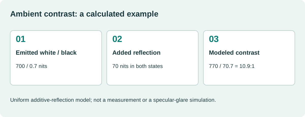
Suppose a display emits 700 nits in white and 0.7 nit in black. If an equal 70-nit reflected contribution is added to both states, the modeled ratio falls from 1000:1 to about 10.9:1.
Increasing emitted luminance can help, but reducing the reflected contribution can also make a substantial difference. The example assumes uniform additive reflection and does not describe a specular image of the sun or a real product test.
A broad sunlight-readable industrial display design review should therefore include reflectance, bonding, coatings, viewing angle, and shading alongside brightness.
Measure after the cover lens
Touch sensors, adhesives, coatings, air gaps, and glass all affect the finished result. Compare the assembly that will ship rather than combining a bare-panel measurement with assumptions about optical losses.
Ask the supplier which surfaces are included in the specified luminance. If the lens is custom, establish an installed-assembly minimum or an agreed correlation supported by measurements.
Optical bonding can reduce internal interface reflections, while anti-glare treatment redistributes reflections. Neither term guarantees a particular ambient contrast. Check industrial TFT optical bonding and the actual coating configuration before drawing conclusions.
Test small text, thin lines, and low-intensity colors too. A large white rectangle can look bright while a gray alarm message disappears in the same conditions.
High brightness has a thermal cost
More backlight power adds heat behind the display. The heat can reduce LED life or bring adjacent components closer to their limits. In sunlight, absorbed external energy adds another load.
Check power draw and temperature at maximum intended brightness inside the finished enclosure. Include the processor and communication hardware running their representative workload.
If thermal control reduces brightness, define how the product remains usable during that reduction. A system that protects its LEDs by becoming unreadable may need a different enclosure, optical design, or operating requirement.
The LCD backlight lifetime and dimming relationship belongs in the same design review as the initial luminance number.
Minimum brightness matters too
A display sized for daylight can be uncomfortable at night if it cannot dim far enough. Check low-level stability, visible flicker, color behavior, and whether important information remains clear.
Automatic brightness needs a suitable sensor location and predictable control behavior. A sensor shaded by the enclosure may command a dim screen while the front is in bright light. A hand passing the sensor should not cause distracting brightness swings.
TI’s ambient-light-sensing reference design illustrates a hardware approach to automatic display brightness. The product still needs application-specific filtering, limits, and manual interaction design.
Define a repeatable acceptance test
| Test condition | Record |
|---|---|
| Stabilized room-temperature measurement | Drive current, warm-up, instrument and geometry |
| Maximum operating temperature | Panel and LED temperatures plus achieved luminance |
| Bright ambient installation | Light, viewing position, UI task and optical assembly |
| Minimum dimming | Stability and readability in low light |
| Automatic mode | Sensor placement, response and manual override behavior |
| Aged or maintenance-limit condition | Required remaining luminance and supporting evidence |
A camera is useful for documenting setup but should not certify nits. Use a suitable calibrated instrument and the specified geometry. Automatic exposure can make two very different screens appear similar.
For user tasks, define success explicitly: read a value at the intended distance, distinguish an alarm from normal status, or complete a setting change without moving into a reflection-free position.
What number should go into the purchase specification?
Use the result of that evaluation: minimum installed luminance at defined conditions, a permitted drive setting, dimming limits, and any aging or thermal requirement. Keep the validation evidence with the approved assembly.
Avoid selecting a larger number merely to cover uncertainty. Extra brightness carries power, thermal, lifetime, and sometimes cost consequences. A requirement connected to measured readability gives the supplier something useful to meet and gives the engineering team a clear basis for acceptance.
A practical handover detail
When comparing samples, hold the installation geometry constant and test both bright and dark content. Record the external light with a suitable method and note whether direct reflections fall across the reading area. Do not compare a shaded sample against another facing a window. If a hood or mount adjustment is part of the solution, include it in the approved assembly and installation drawing. A readability improvement dependent on an undocumented field adjustment is difficult to reproduce during acceptance or replacement.
Sources and image credit
Primary technical references are linked beside the relevant claims. Numerical examples are calculations under the stated assumptions. The original diagram explains the design method; neither it nor the photograph represents a qualification test performed by this site.
Hero photograph: Lance Cheung / USDA, Public domain — U.S. federal government work. Resized and JPEG-compressed.