Industrial TFT Display Validation Checklist

Industrial TFT display validation should prove that the screen works in the finished product, not only that the module turns on. Many field problems come from the interaction between LCD, touch sensor, cover glass, enclosure, cable, power, software, lighting, and user behavior. A display that passes a quick bench test can still fail when installed in a cabinet, vehicle, handheld device, or outdoor kiosk.
A written checklist keeps the team honest. It helps hardware, software, mechanical, quality, and supplier teams test the same assumptions. It also creates evidence for future service and product changes.
1. Confirm documentation
Start with documents: datasheet, drawing, connector pinout, timing table, initialization sequence, backlight circuit notes, touch controller information, optical specs, environmental ratings, and change notice policy. Missing documentation is a risk by itself.
Record the exact display revision, firmware version, touch settings, cable, cover glass, and assembly state tested. Future engineers need to know what was validated.
2. Power and startup
Check power rails at the display connector. Confirm voltage, ripple, inrush, sequencing, reset timing, and backlight enable. Test cold start, warm start, brownout, and recovery after power loss.
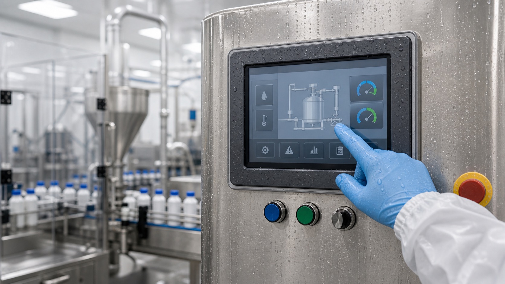
The screen should show clear behavior during boot. If the UI takes time to load, users should not see a confusing blank state. For equipment with safety or process impact, define what the display shows when communication is lost.
3. Optical performance
Test brightness, contrast, viewing angle, color appearance, uniformity, and readability with the final cover glass. Use real lighting conditions: factory lamps, window light, sunlight, vehicle cabin light, or laboratory light depending on the product.
A bare LCD is not enough. Touch layers, air gaps, bonding, coatings, and bezels change readability. If the product needs sunlight readability, test outdoors with the final UI.
4. Touch validation
Test touch with bare fingers, defined gloves, wet fingers, cleaning residue, and the final enclosure ground. Check edges, corners, multi-touch if used, false touches, missed touches, and operation near electrical noise sources.
Touch should be tested with the real UI. A simple touch test page can pass while small buttons in the final application still cause errors. For outdoor or washdown systems, include water rejection and cleaning mode behavior.
5. Temperature and humidity
Test cold start, high temperature operation, storage recovery, thermal cycling, and humidity or condensation if relevant. LCD response, backlight brightness, touch sensitivity, adhesives, and gaskets can all change with temperature.
For battery devices, include low battery and cold battery behavior. For outdoor or vehicle systems, include sun load or enclosure heating where possible. Wide temperature claims should be proven in the product, not only accepted from a datasheet.
6. Vibration, shock, and mounting
Validate the display in the real mounting structure. Check for light leakage, connector movement, cable strain, glass stress, rattling, and touch changes after vibration or shock. A module can be strong but fail if the enclosure twists it.
For impact-resistant products, test the full front stack. Cover glass, edge support, bonding, bezel, and gasket all affect survival.
7. EMC and electrical noise
Run the display while motors, relays, drives, radios, chargers, or switching power supplies operate. Watch for flicker, resets, touch noise, communication errors, and display artifacts. Test cable routing as it will be shipped.
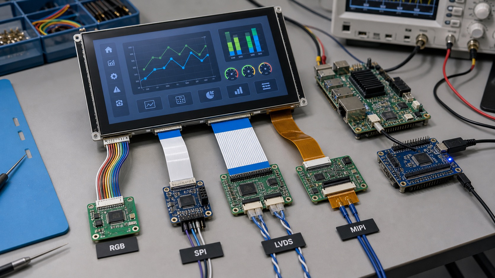
Interface choice matters. Long cables, cabinet doors, and noisy environments may require LVDS or other robust paths. Do not validate on a short bench cable if the final product uses a different route.
8. Cleaning and surface durability
Use the same cleaning agents, cloths, gloves, and pressure expected in the field. Check haze, scratches, coating damage, seal edges, touch response, and cosmetic change. For medical, food, or laboratory equipment, cleaning behavior can be as important as brightness.
IP rating does not prove chemical resistance. Test the actual material stack. This is especially important for laboratory equipment displays and washdown HMIs.
9. Software and UI behavior
Test the final UI for readability, touch target size, alarm state, language expansion, boot messages, error recovery, and service pages. A display is not validated if only a logo or color bar was shown.
Include worst-case content: long translated labels, active alarms, low brightness, night mode, dense graphs, and communication loss. Users judge the finished workflow, not the display module.
10. Service and replacement
Check whether the display can be replaced without damaging cables, gaskets, or enclosure parts. Confirm whether touch calibration, firmware settings, or brightness configuration must be restored after replacement.
Document the approved supplier, part number, revision, drawings, settings, and test results. If a replacement is needed years later, this record reduces risk.
Final review
Validation is complete only when the display passes in the product environment. That includes the enclosure, cable, power supply, software, user workflow, and service plan. Shortcuts during validation often become expensive field issues.
For new projects, use the validation plan together with a clear industrial TFT specification. Specification defines the target; validation proves the target was met.
Sign-off evidence
Validation should end with evidence, not only opinions. Keep photos, test conditions, firmware versions, display settings, measurement results, and pass or fail notes. If a test is skipped, record why. This makes future design changes easier to judge and gives service teams a baseline when field units come back.
It is also useful to separate engineering validation from production checks. Engineering validation proves the design is suitable. Production checks confirm each unit was built correctly. A short factory display test should not replace deeper environmental and usability validation.
When to repeat validation
Repeat at least part of the validation when the LCD cell, touch controller, cover glass, cable, adhesive, firmware, processor board, enclosure, or cleaning process changes. Small changes can affect touch performance, brightness, EMI behavior, or sealing. A supplier replacement that looks equivalent on paper may still need confirmation in the finished product.
Validation should also be repeated after serious field display issues. The goal is not only to repair one unit, but to learn whether the original test plan missed a realistic condition. Field returns should be grouped by symptom, environment, runtime, and product revision, because repeated patterns often reveal more than a single failed sample. A dim screen, false touch report, or intermittent cable fault should update the next test plan instead of remaining a one-off support note.
FAQ
Is a display datasheet enough for validation?
No. The datasheet is a starting point. The finished product must be tested with the final glass, enclosure, cable, power, software, and environment.
What should be tested first?
Start with power, reset, backlight, and basic image output. Then validate optical, touch, temperature, EMC, mechanical, and UI behavior.
Who should join display validation?
Hardware, software, mechanical, quality, supplier, and real users should all contribute because display problems often cross team boundaries.