MIPI DSI Display Bring-Up Checklist
MIPI DSI can be an excellent interface for embedded TFT displays, but bring-up can be less forgiving than older display paths. A blank screen may come from power rails, reset timing, lane count, lane order, command sequence, pixel format, clock settings, driver configuration, or a simple connector orientation mistake. Without a checklist, teams can lose days chasing the wrong layer.
The notes below are for teams bringing up a MIPI DSI TFT module on an embedded board, especially when the finished product needs repeatable builds rather than a one-off demo.
Start with documentation
Before powering anything, collect the panel datasheet, connector pinout, recommended power sequence, initialization commands, timing table, lane count, voltage requirements, and reference driver if available. If the display supplier cannot provide these details, risk is already higher.
MIPI panels often need specific initialization commands. A display with the same size and resolution may not use the same controller or sequence. Do not assume that a driver for a similar panel will work without review.
Confirm power rails
Check every required supply rail with a meter or scope. Some panels need logic voltage, analog voltage, backlight supply, and reset control in a defined order. If the rails ramp too slowly, too quickly, or in the wrong order, the panel may not initialize.
Measure at the connector, not only at the regulator. A voltage that looks correct near the power supply may sag at the FPC after cable loss or inrush. Confirm that the backlight supply is separate from panel logic if the design uses different domains.
Check reset and enable timing
Reset timing is a common bring-up failure. The panel may require reset to be held low after power is stable, then released before the initialization sequence. If the host sends commands too early, the panel may ignore them.
Use a scope to confirm reset, enable, and power rails. Software logs alone do not prove the physical timing is correct. If a GPIO is inverted or delayed by boot firmware, the driver may appear correct while the hardware sees the wrong sequence.
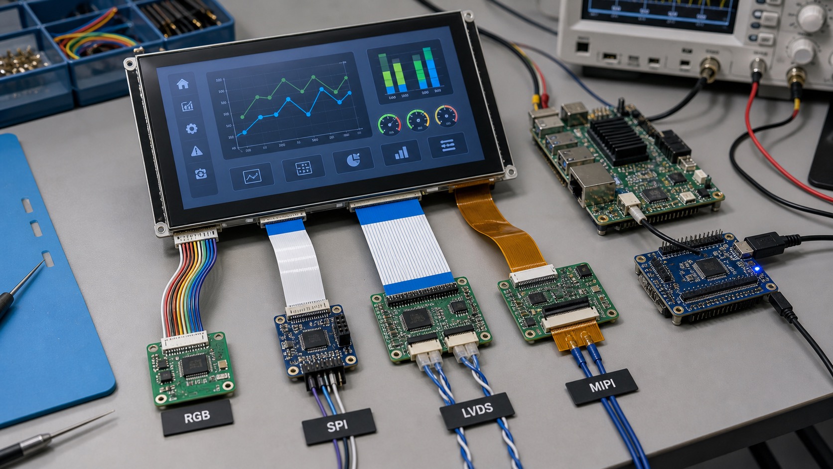
Verify lane count and lane order
MIPI DSI panels use one or more data lanes plus a clock lane. The lane count in software must match the panel and board wiring. Lane polarity, order, and routing should be checked against the schematic and layout.
If the panel shows no image, unstable image, or intermittent behavior, review lane configuration early. A mismatch can look like a software driver problem. High-speed routing also needs controlled impedance and short, clean connections.
Review display mode
MIPI DSI can use command mode, video mode, or vendor-specific behavior. The host configuration must match the panel. Video mode panels may require continuous timing, while command mode panels may rely on explicit updates.
Confirm pixel format, resolution, porch values, sync timing, refresh rate, and color order. A wrong RGB/BGR setting may produce swapped colors. Wrong timing may produce flicker or a shifted image. The same issues appear in other interfaces, but MIPI adds more configuration layers.
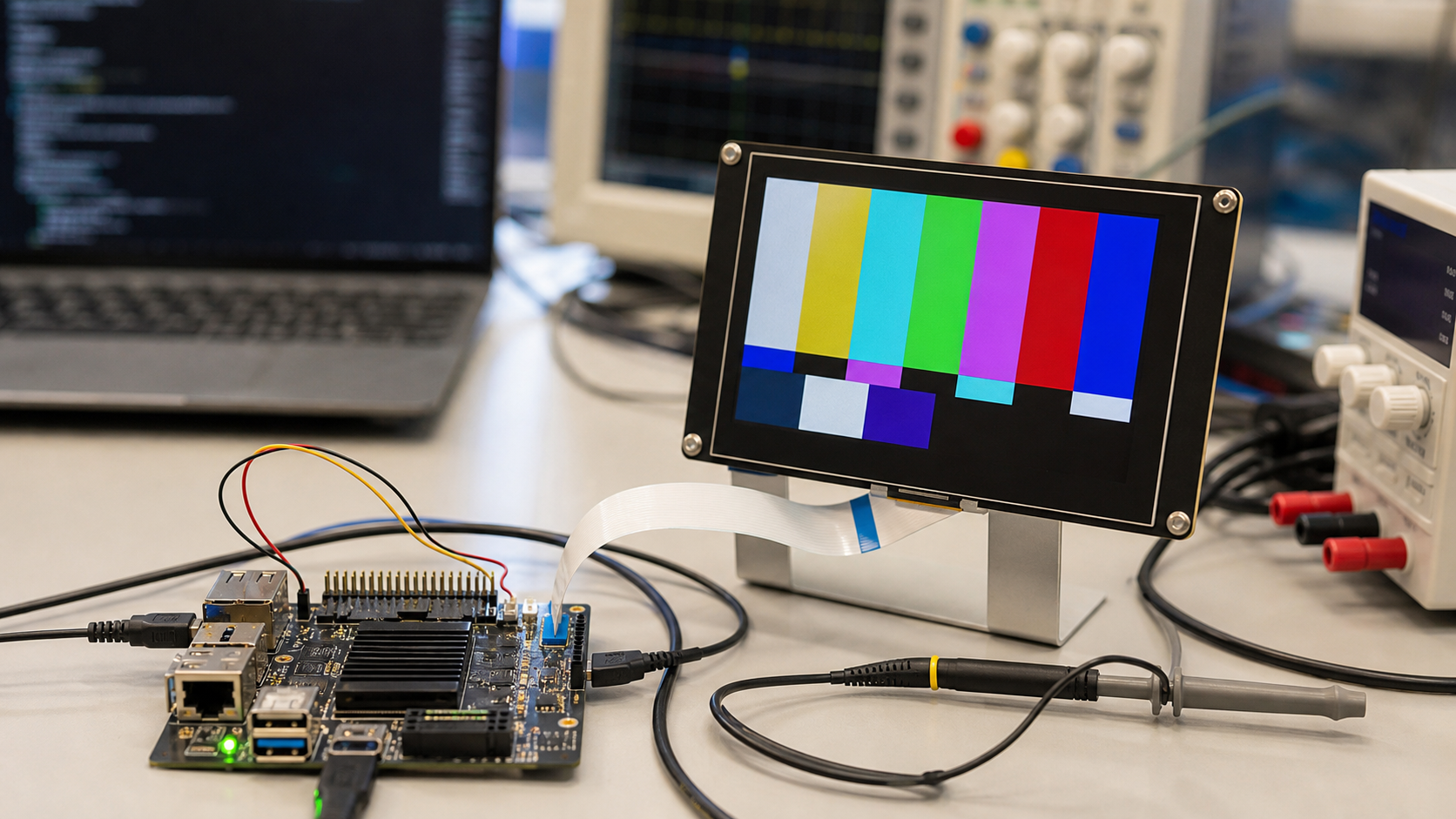
Use simple test patterns first
Before loading the final UI, show solid colors, gradients, checkerboards, and moving rectangles. These patterns help identify color channel swaps, tearing, missing lines, partial updates, and timing problems.
Keep the test pattern code available after launch. Future production issues are easier to diagnose when engineers can switch from the full UI to a known display test. This is part of a disciplined industrial TFT display validation process.
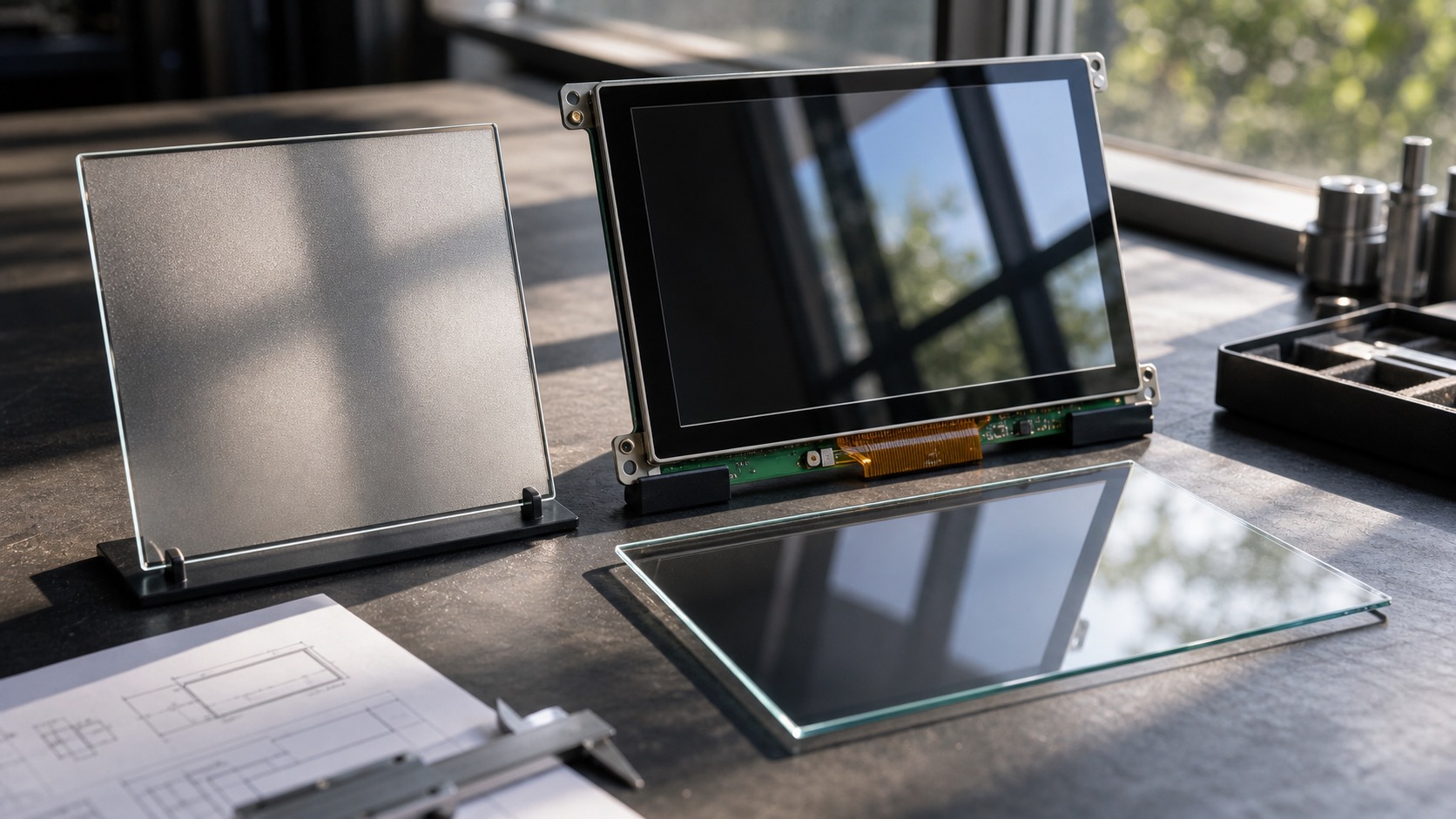
Backlight is not the same as display data
A glowing backlight does not prove the panel is receiving MIPI data. A blank white or black screen can mean the backlight works while the LCD is not initialized. Confirm backlight enable and PWM separately from panel commands.
Likewise, an image without backlight may be present but invisible. Use a flashlight at an angle if needed. Separating LCD logic from backlight control prevents misleading conclusions.
Driver and kernel configuration
For Linux systems, review device tree settings, panel driver, DSI host configuration, regulator names, GPIOs, clocks, and reset timing. Small naming errors can prevent the driver from probing. Logs are useful, but they should be matched against scope measurements.
If the supplier provides a command sequence, document where it is applied in the driver. Keep version control notes. Industrial products may need the same bring-up knowledge years later when a kernel, processor, or display revision changes.
EMC and cable behavior
MIPI prefers short, controlled routing. If the display is connected by a long cable or through a hinge, risk increases. Industrial products sometimes push MIPI beyond the simple phone-style layout it was designed for. In those cases, consider shielding, ground reference, connector quality, or a bridge to LVDS/eDP for longer paths.
Do not validate only with an open bench cable if the final product has a folded FPC, metal enclosure, or nearby switching power supply. Test the finished mechanical stack.
Common failure signs
A fully blank screen may point to power, reset, lane, or driver probe issues. Wrong colors often suggest pixel format or lane mapping. Flicker can come from timing, power noise, or signal integrity. Random failures after warm-up may suggest marginal routing or thermal behavior.
Keep notes as each issue is solved. A bring-up log with scope captures, driver versions, command sequences, and final timing values becomes useful evidence when the board is revised or the display supplier changes.
Supplier questions
Ask whether the panel has been tested on your processor family, whether a reference driver exists, whether initialization commands change between revisions, and whether the display controller is planned for long-term supply. Also ask how PCNs are handled if the LCD cell or driver IC changes.
For industrial programs, the bring-up checklist is not just for the first prototype. It becomes part of the support package for future builds, replacements, and software updates.
Production handoff
After the display works, freeze the working configuration. Save the driver version, device tree, command sequence, timing values, lane settings, and power sequence in the project documentation. Also keep photos of the cable orientation and connector lock. MIPI issues are easy to reintroduce when a board is revised or a kernel is updated.
Production testing should include more than a boot logo. A short automated display test can show colors, a moving object, and a backlight dimming sweep. This gives manufacturing a simple way to catch cable, panel, or configuration errors before units leave the line.
FAQ
Why does a MIPI DSI display show only backlight?
The backlight may be powered while the LCD logic is not initialized. Check panel power, reset, lane configuration, command sequence, and driver logs.
Can MIPI DSI be used in industrial displays?
Yes, especially for compact embedded products. For long cables or noisy environments, validate signal integrity carefully or consider LVDS.
What is the first thing to test during bring-up?
Confirm power rails and reset timing at the connector, then verify lane configuration and show simple test patterns before loading the final UI.