Preventing Condensation and Fogging in Sealed TFT Displays
A sealed display can pass a water-spray test and still fog on a cool morning. Liquid-water ingress and internal condensation are different failure mechanisms. Air and materials inside the enclosure can already contain enough moisture to form droplets when the cover lens cools.
Effective TFT condensation prevention starts with two measurements: the moisture level of the internal air and the temperature of the coldest relevant surface. Seals, vents, heaters, and desiccants address different parts of that problem. Choosing one before identifying the moisture path can produce a short-lived improvement.
Locate the water before changing the enclosure
First determine which surface is fogging. Exterior condensation can often be wiped away. Moisture behind the cover lens cannot. A persistent milky patch may instead be adhesive damage, contamination, or another optical defect.
Photograph the onset and recovery without opening the unit. Record whether fog appears after rain, shutdown, washdown, transport from cold storage, or a rapid weather change. Opening the enclosure changes its moisture balance and can erase the evidence.
| Observation | Plausible mechanism to investigate | Useful next measurement |
|---|---|---|
| Fog on the outside only | Exterior glass below ambient dew point | Exterior surface temperature and ambient humidity |
| Internal haze after shutdown | Cooling surface meets moist internal air | Internal dew point and lens temperature over time |
| Local droplets near a cable entry | Leakage or localized cold surface | Entry inspection plus controlled leak and thermal checks |
| Fog after repeated daily cycles | Moisture exchange or material desorption | Internal humidity trend across several cycles |
| Patch remains after controlled drying | Optical-stack damage or contamination | Inspection of lens, bond line, and polarizer |
Treat these as investigation branches, not diagnoses from appearance alone. Several mechanisms can coexist in the same unit.
Compare surface temperature with dew point
Dew point is the temperature at which the air reaches saturation for its moisture content and pressure. A surface at or below that point can collect condensate. Vaisala’s dew-point explanation gives the underlying relationship and a calculation tool.
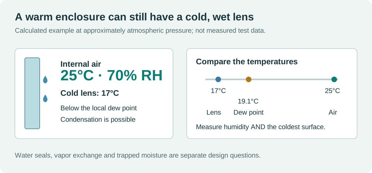
As a calculated example, air at 25°C and 70% relative humidity has a dew point of roughly 19.1°C. A lens that cools to 17°C is therefore at risk even if the processor board remains warm. At 25°C and 50% RH, the dew point is about 13.9°C. These approximations use a standard Magnus-form calculation over liquid water; they are not chamber measurements.
The useful quantity is the difference between the coldest surface temperature and the local dew point. Include measurement uncertainty and thermal lag when deciding the required margin. A humidity sensor beside a warm processor may not describe conditions in the narrow space behind the cover lens.
A water seal does not establish vapor tightness
An ingress-protection result applies to a defined assembly and test. It does not, by itself, establish a long-term water-vapor transmission rate or prove that the unit was dry when closed. Polymers, gasket interfaces, cable routes, and service openings all need consideration.
Temperature changes also alter enclosure pressure. Repeated pressure differences can stress seals and encourage exchange through imperfect interfaces. A pressure-equalizing vent can reduce that stress, but its performance depends on placement, airflow capability, contamination, and enclosure volume.
Gore describes how its protective membrane vents manage pressure and moisture. The engineering implication is to model a vent as an exchange path, not as a dehumidifier. It cannot guarantee dry internal air when the external environment is persistently humid, and it does not replace a sound seal against bulk liquid.
Select the countermeasure for the actual mechanism
| Measure | What it can address | Limitation to design around |
|---|---|---|
| Improved seals and cable entries | Bulk-water leakage | Does not remove moisture trapped during assembly |
| Membrane vent | Pressure equalization and moisture exchange | Exchange may be slow; contamination and persistent humidity matter |
| Desiccant | A defined moisture load in a serviceable volume | Finite capacity; needs sizing and replacement or regeneration |
| Controlled heater | Keeps selected surfaces above dew point | Requires power, thermal limits, and a fault strategy |
| Optical bonding | Removes a front air gap that can fog | Does not dry the enclosure or protect every interface |
| Dry assembly process | Reduces initial trapped moisture | Does not stop later ingress or material moisture release |
Desiccant sizing should include moisture initially in the air, moisture released by materials, expected ingress, and the interval between service visits. A small packet that clears a prototype overnight is not evidence of a multi-year solution. Secure it where it cannot abrade the electronics or obstruct a vent.
For a heater, verify the temperature at the vulnerable surface. Heating the circuit board may leave the lens edge cold. Review thermal gradients, adhesive limits, power consumption, and behavior when the sensor or heater fails. Avoid curing fog by pushing another component beyond its temperature rating.
Bonding solves one cavity, not every moisture problem
Removing the air gap between a cover lens and LCD can eliminate condensation in that particular space. It also changes the optical and mechanical behavior of the assembly. Moisture can still affect exposed edges, connector regions, rear electronics, or an unsuitable adhesive system.
Specify edge treatment, adhesive compatibility, process controls, and environmental qualification with the bonding supplier. Our optically bonded industrial displays discussion covers the broader tradeoffs. Do not describe bonding as a guarantee that an entire enclosure is waterproof or immune to fogging.
Cleaning exposure creates another variable. Surfactants, solvents, and residues can affect coatings, gasket materials, and vent behavior. Use the actual agents and application method from the product’s industrial display cleaning requirements.
Test the transition that produces the problem
A constant-temperature humidity soak can miss a failure triggered by rapid cooling. Build the test around the field sequence: warm operation followed by shutdown, a cold unit entering humid air, or a hot enclosure exposed to cooler rain.
Instrument internal air temperature and humidity, the cover lens, and relevant metal surfaces. Avoid routing sensor wires in a way that creates a new leak. Log the data fast enough to capture the transition, and synchronize it with photographs of the display.
Define pass criteria before running the test. Examples include no obscuration of critical text, no liquid on vulnerable electronics, acceptable touch behavior, and complete recovery within a specified interval where temporary exterior fog is permitted. The actual limits must follow the use case.
Repeat the sequence after realistic aging, seal assembly, cable installation, and cleaning exposure. Include both powered and unpowered states. Outdoor TFT environmental validation should capture the final assembly, while wide-temperature display integration covers related startup and thermal concerns.
What if fog returns after adding a vent?
Check whether the vent is correctly installed and exposed to useful airflow, then compare the measured moisture and surface-temperature traces. The lens may cool faster than moisture can leave. External air may be equally humid. A hidden water path or moisture-releasing material may dominate the load.
That evidence tells you whether to improve drying, change vent placement, address leakage, or control a cold surface. The successful design is the one that remains inside its moisture and temperature limits through the actual operating cycle, not merely the one that looks clear at room temperature.
Sources and photograph
Vaisala and Gore sources are linked beside the relevant principles. The numerical example and enclosure illustration are explanatory, not product test results.
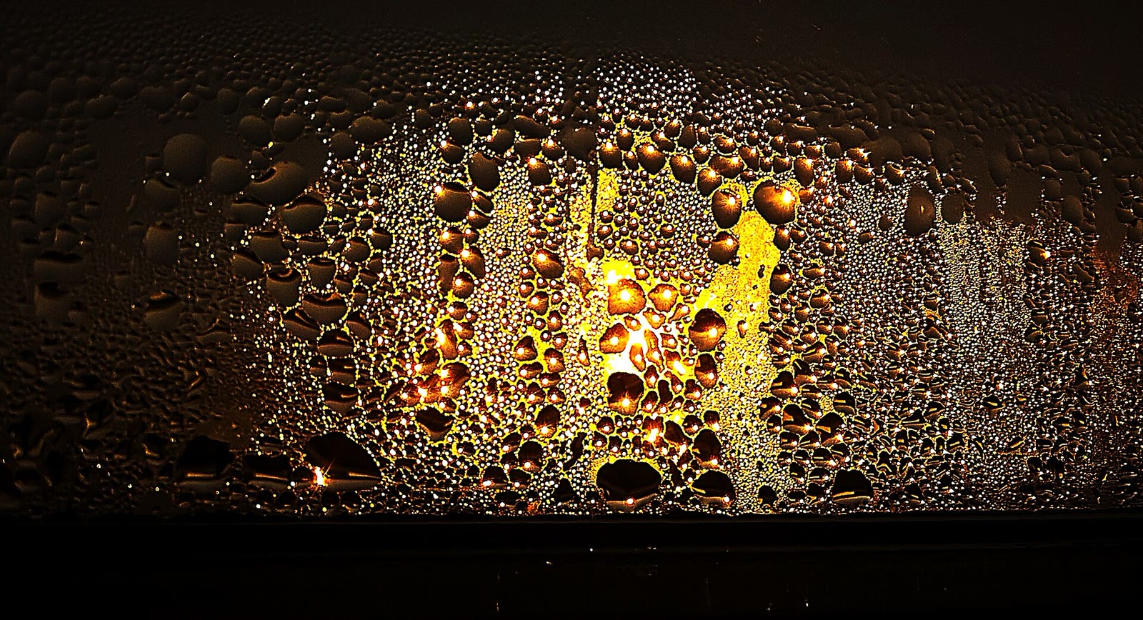
Hero photograph: Tarasna0922, condensation on a window at sunset, CC BY-SA 4.0. Resized and JPEG-compressed; the adapted photograph retains that license.