How to Qualify a Second Source for an Industrial TFT Module
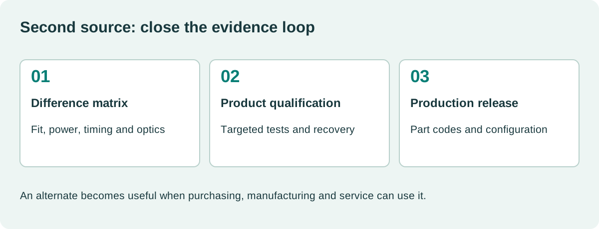
Two TFT modules can share diagonal size, resolution, and connector pitch while requiring different power, timing, mounting, or firmware. A second source becomes useful only when the product can accept it under a controlled configuration.
Start qualification before the primary module becomes unavailable. That leaves time to identify real differences, test them in the finished product, and agree which substitutions can occur in production. An untested part on an approved vendor list is not an operational fallback.
Decide what kind of interchangeability is required
A drop-in replacement should work without product changes under the defined configuration. A qualified alternate may require a cable, firmware setting, bracket, or separate assembly code. Both can be useful, but they have different manufacturing consequences.
Write the permitted changes explicitly. If service staff must identify the panel and choose different firmware, the replacement process needs that information.
| Compatibility area | Evidence |
|---|---|
| Mechanical | Outline, image position, thickness, supports and tolerances |
| Electrical | Rails, pinout, sequencing, current and grounding |
| Video | Timings, pixel format, mapping and initialization |
| Optical | Luminance, contrast, viewing behavior and uniformity |
| Touch | Controller, firmware, cover stack and tuning |
| Environmental | Actual assembly performance under required conditions |
| Supply | Traceability, change notification and lifecycle terms |
Use the current industrial TFT module requirements as the baseline. If the baseline is incomplete, qualification will otherwise become a comparison with one convenient sample rather than the product’s needs.
Build a difference matrix before ordering tests
Compare the approved primary documents with the candidate’s controlled documents. Mark each requirement as identical, different but acceptable, unsupported, or awaiting evidence.
Do not call two unspecified values equal. If one supplier gives a typical brightness and another gives a minimum, request comparable evidence. The same caution applies to temperature, backlight life, and visual defect rules.
Record which differences require testing and which can be resolved through drawing or specification review. That makes the plan proportional to risk and prevents repeated measurements of already established facts.
Include the host board, cable, touch stack, and enclosure revisions. The alternate is being qualified for that system, not for an abstract connector.
Mechanical compatibility needs a tolerance review
Check active-area position, mounting datums, frame thickness, connector access, and cable bending. A slightly shifted image can expose printed lens edges or hide important pixels.
Use the TFT drawing tolerance review to evaluate the full stack. A sample that fits at room temperature is not proof of worst-case fit.
Inspect pressure artifacts after final tightening. Differences in frame stiffness or contact surfaces can change how enclosure loads reach the LCD cell.
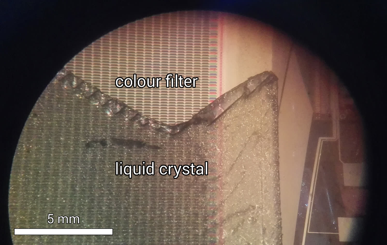
For bonded assemblies, compare adhesive system, cover glass, edge treatment, and repair strategy. Matching the LCD cell does not make the complete optical stack equivalent.
Validate electrical behavior at the connector
Confirm every pin and voltage before power is applied. A matching connector can conceal different assignments. Check power sequence and reset polarity from the actual candidate specification.
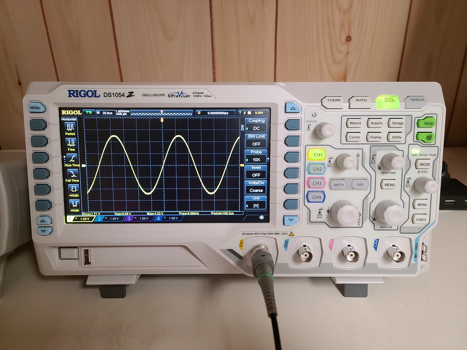
Measure startup, steady-state current, backlight load, and relevant supply transitions. Compare short interruptions and warm restarts as well as a clean cold boot.
If the alternate requires different initialization, control that selection in manufacturing and service. Automatic identification should be reliable and documented rather than inferred from a nonunique label or an incidental timing behavior.
The embedded display startup diagnostic helps organize evidence when an alternate works inconsistently.
Compare optics through the final assembly
Use the same application image, drive conditions, measurement setup, and stabilization method. Compare minimum requirements, not whether the candidate looks slightly more pleasing.
Check off-axis gray behavior, dark detail, small text, bright ambient readability, and low-level dimming. An alternate can meet on-axis luminance and still change an operator’s interpretation.
Agree visual defect criteria separately. A different pixel or cluster allowance may be commercially acceptable, but it is not an invisible difference.
| Comparison | Condition to hold constant |
|---|---|
| Luminance | Backlight setting, temperature and optical stack |
| Uniformity | Measurement points and formula |
| Color or gray behavior | Test image and viewing geometry |
| Dimming | Command, supply and low-light environment |
| Touch | Firmware, gloves, grounding and cover lens |
| Application readability | Actual tasks and working positions |
Record instrument results alongside controlled photographs. A phone’s automatic exposure can make different panels appear artificially similar.
Qualification is not incoming inspection
Environmental and usability tests establish whether the alternate design is suitable. Receiving checks establish whether delivered production units conform to the approved alternate.
Test the differences that can affect thermal, moisture, vibration, cleaning, EMC, power, and operator behavior. Some differences may require broad revalidation; others justify a focused test with documented reasoning.
The industrial TFT qualification checklist supplies a structure for this review. If the product has formal certification obligations, assess how the component change affects the applicable evidence.
Avoid claiming full equivalence from a short bench run or from the candidate supplier’s test report for a different configuration.
Include supplier change management
NXP’s change-management description provides a useful example of formal review for changes affecting fit, form, function, quality, or reliability. It applies to NXP’s products, not automatically to a display assembly.
Ask each display supplier which changes trigger notification and what approval or last-order terms apply. Include changes to the cell, driver, LEDs, polarizer, FPC, touch firmware, and assembly process where relevant.
A second supplier depending on the same upstream cell or factory may not remove the supply risk the team expects. Discuss upstream dependencies without assuming that different sales brands mean independent manufacturing.
Run a production trial
Build a controlled quantity using the normal assembly process. Verify part identification, cable selection, firmware programming, fixture compatibility, inspection limits, and packaging.
Track the alternate through production records so field data can be separated by source. If the two parts are genuinely interchangeable, the records should still identify which was installed.
Update the display incoming acceptance procedure for any source-specific checks. Inspectors should not have to guess which optical or mechanical limits apply.
Close with an approval that manufacturing can use
Release a signed compatibility matrix, test evidence, configuration instructions, approved part codes, and any restrictions. State whether mixing sources within a product lot is permitted and how service replacements are selected.
Keep remaining limitations visible. An alternate approved only for indoor units should not silently enter outdoor builds.
The useful outcome is a reproducible fallback: purchasing can order it, manufacturing can assemble it, software can configure it, and service can replace it. That is what turns a second-source exercise into actual resilience for a long-life display program.
A practical handover detail
Give the production trial an explicit exit review. Confirm that the alternate’s part code appears correctly in purchasing, the assembly instruction names the right cable, and the test fixture recognizes the intended configuration. Check the spare-parts record as well. An alternate can pass every engineering test and still fail as a fallback if service orders the wrong harness. Closing those administrative details alongside the technical evidence makes the approved replacement usable when the primary supply is actually interrupted.
Sources and image credit
Primary technical references are linked beside the relevant claims. Numerical examples are calculations under the stated assumptions. The original diagram explains the design method; neither it nor the photograph represents a qualification test performed by this site.
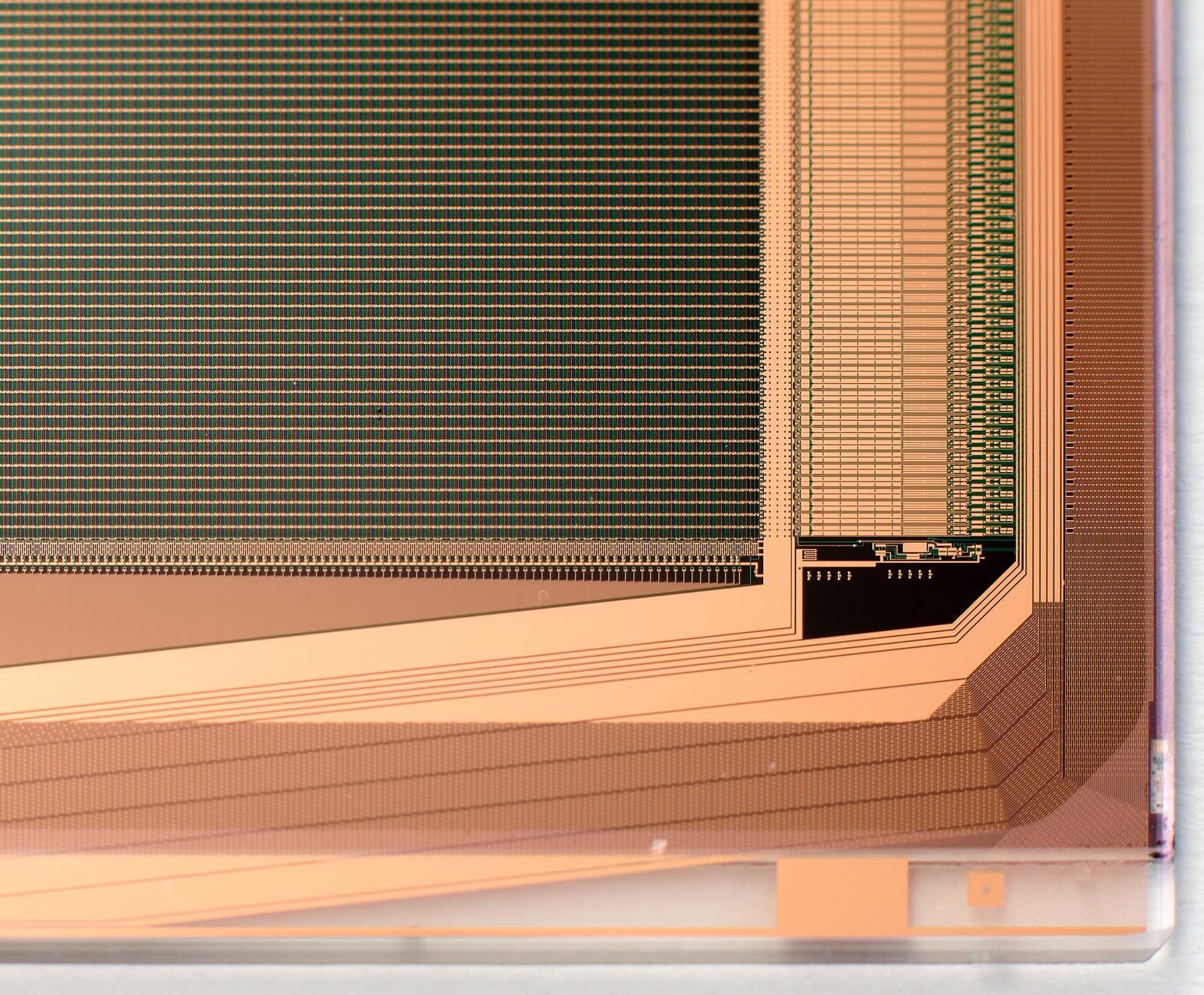
Hero photograph: Sdk16420, CC BY-SA 4.0. Resized and JPEG-compressed. This adapted photograph remains under the linked ShareAlike license.