SPI vs MCU vs RGB Interfaces for Small TFT Displays
A small TFT does not necessarily need a continuous video interface. If the image changes only when a value or menu changes, a module with local display memory can save host pins and traffic. If the screen contains fast trends and large transitions, the same arrangement can become the bottleneck.
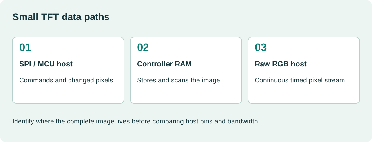
The SPI, MCU, and RGB decision is fundamentally about where the complete image is stored and how new pixels reach it. Before comparing connector pin counts, identify the display controller, its memory, and the host’s available peripherals.
Three names describe different data paths
SPI is a serial transaction interface. A typical small display accepts commands and pixel writes into controller memory. “MCU interface” often refers to an 8080-style or 6800-style parallel command/data bus. Confirm the exact protocol because the label alone is incomplete.
A raw RGB interface usually receives a continuous pixel stream with timing signals. Its source must provide valid video at the required cadence even when the user interface is stationary.
| Interface | Typical image storage | Main host obligation | Common constraint |
|---|---|---|---|
| SPI command display | Module controller RAM | Send changed areas | Serial payload rate |
| Parallel MCU bus | Module controller RAM | Execute command/data transactions | Pin count and bus timing |
| Raw RGB | Host framebuffer | Maintain continuous scanout | RAM bandwidth and timing |
| RGB with separate setup bus | Host plus panel registers | Configure and stream correctly | Two independent interfaces |
There are exceptions. Read the module block diagram and controller specification rather than assuming the architecture from the connector name.
Calculate the work required for one update
A 480 × 272 RGB565 image contains 261,120 bytes. At a hypothetical 40 Mbit/s serial payload rate, transferring those bytes takes at least 52.2 ms. That is roughly 19 full frames per second before command overhead, transaction gaps, rendering, or contention.
This is a mathematical lower bound, not a permitted clock for a particular module. Use the controller’s rated serial clock and the measured efficiency of the host implementation.
A 100 × 40 RGB565 value box contains only 8,000 bytes. At the same ideal rate, its transfer takes 1.6 ms. Partial updates can therefore make a serial display feel responsive without sustaining full-screen animation.
Our TFT framebuffer bandwidth examples help separate storage, rendering, and transport costs. Count all three when evaluating a proposed interface.
Local display RAM changes the firmware structure
A controller with local memory can continue scanning the screen while the host prepares another update. The host may need only small working buffers, depending on the graphics library and drawing approach.
That does not make updates instantaneous. Large screen transitions still require traffic, and the controller may scan pixels while they are being changed. A tearing-effect output or another documented synchronization method can help, but its use depends on the controller and host timing.
LVGL’s display-interface documentation distinguishes partial, direct, and full rendering. Choose a mode that matches the hardware. A partial drawing buffer does not remove the need for a complete scanout image in a raw RGB design.
Plan who owns a buffer while DMA is transmitting it. Reusing that memory before transfer completion can create corruption that looks like a panel problem.
Parallel MCU buses trade pins for transaction speed
An 8-bit or 16-bit command/data bus can move pixel writes faster than a narrow serial connection under suitable timing. The actual advantage depends on write-cycle constraints, host peripheral support, routing, and software overhead.
Check setup and hold times, read/write strobes, command/data selection, voltage levels, and whether readback is supported by the assembled module. Read turnaround can be more demanding than simple writes.
The host may support an external memory controller that can generate the required cycles. Confirm how it handles bus width, address mapping, byte lanes, and DMA. A controller that exists in the processor family may not exist in the exact package or part selected.
Also reserve pins for the rest of the product. A display interface that consumes the only practical external-memory bus can create a much larger system tradeoff.
Raw RGB needs continuous service
An RGB panel is attractive when the host has a suitable LCD controller and enough memory bandwidth. It avoids sending individual drawing commands to a separate display controller and can support flexible graphics composition.
The cost is continuous scanout and a wider physical interface. The host must meet pixel clock, blanking, synchronization, bus mapping, and supply-sequence requirements. Correct resolution alone is insufficient.
ST’s LTDC application note discusses controller and memory constraints for supported STM32 devices. Use its device-specific methods when working with that architecture; do not treat a product-family maximum as guaranteed on every board.
Compare RGB and LVDS integration if the panel moves away from the host. A short-board interface and a cabinet-door cable are different routing problems.
Initialization still matters after the bus works
A command transaction captured on a logic analyzer proves that something was sent. It does not prove that the panel accepted the right pixel format, orientation, address window, or sleep-exit sequence.
Start with a small solid rectangle at a known coordinate. Then add color bars and a full image. Check byte order separately from red/blue channel mapping. Those errors require different fixes.
| Symptom | First checks |
|---|---|
| Correct shape, wrong colors | Pixel format, byte order, channel mapping |
| Shifted image | Address window, offsets, timing |
| Sporadic corruption | Transfer completion, signal margin, buffer ownership |
| Tearing | Scan/write interaction and synchronization |
| Works only after reset | Initialization and power sequence |
| Slow page changes | Payload size, effective bus rate, redraw policy |
Use a small TFT black-screen diagnostic workflow when no pattern appears. Avoid changing the graphics library and the electrical configuration simultaneously.
Measure the interaction users notice
A user does not experience a bus specification. They experience delay after pressing a button, the time required to change a page, and whether a trend moves cleanly.
Benchmark those tasks with logging, communication, and storage enabled. Record actual transferred bytes, DMA occupancy, CPU time, and the longest input-to-feedback delay. An idle demonstration can hide contention that appears in the finished instrument.
Choose SPI when its partial-update behavior fits the workload. Consider a parallel command bus when more transaction throughput is needed and pins are available. Choose raw RGB when the host can sustain its timing and memory demands. Preserve the measurements and assumptions so the next firmware revision does not quietly exceed the original budget.
A practical handover detail
Keep the benchmark firmware small enough to explain. Record the display command sequence, transfer chunk size, DMA configuration, and whether the measured time includes rendering or only transmission. Otherwise, two teams may quote different frame rates for the same hardware because one starts timing after the image is ready. For an input-response check, timestamp the accepted touch and the completed visible update. That end-to-end result connects the interface choice to the delay an operator actually experiences.
Sources and image credit
Primary technical references are linked beside the relevant claims. Numerical examples are calculations under the stated assumptions. The original diagram explains the design method; neither it nor the photograph represents a qualification test performed by this site.
Hero photograph: Viswesr, CC BY-SA 3.0. Resized and JPEG-compressed. This adapted photograph remains under the linked ShareAlike license.