TFT Display Interface Selection: RGB, SPI, LVDS, and MIPI
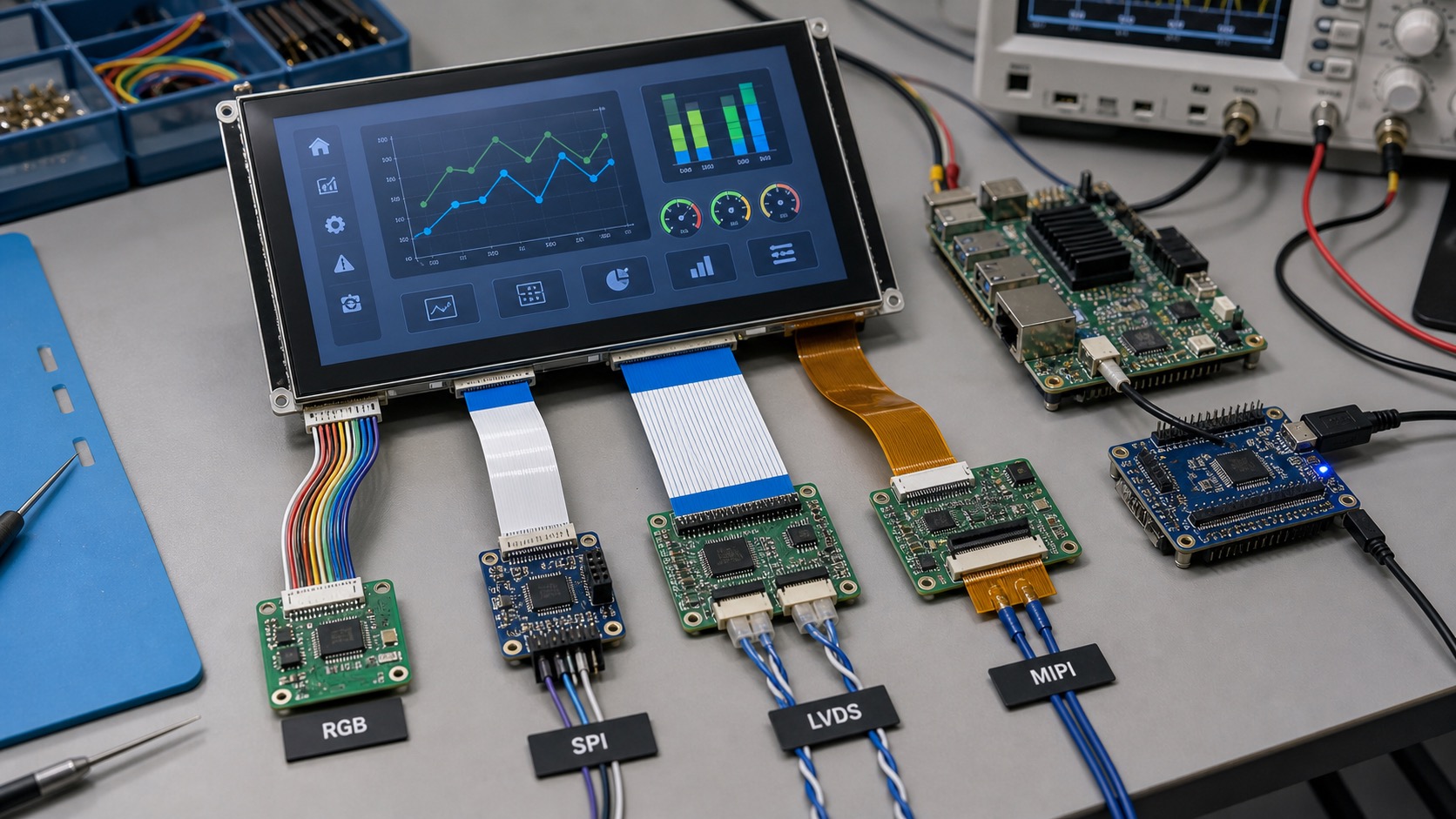
Selecting the TFT display interface is one of the decisions that can quietly shape the entire product. The interface affects processor choice, PCB layout, cable routing, software drivers, EMC behavior, refresh rate, and long-term replacement options. RGB, SPI, LVDS, and MIPI can all be good choices, but they fit different industrial TFT display products.
A display interface should be selected together with the screen size, resolution, UI complexity, and mechanical architecture. Waiting until after board layout or enclosure design can create expensive changes.
SPI for simple displays
SPI is simple and widely supported by microcontrollers. It uses few pins and works well for small displays with limited update needs. Many compact instruments, simple status panels, and low-cost embedded devices use SPI.
The limitation is bandwidth. Full-screen updates can be slow, especially at higher resolution. If the UI uses animation, video, or frequent screen changes, SPI may feel sluggish. Partial updates and efficient UI design can help.
RGB for classic embedded HMIs
Parallel RGB is common in embedded systems. It can drive mid-size TFTs such as 4.3-inch and 7-inch modules with good performance. Many microprocessors include RGB display controllers.
RGB uses more pins and needs careful routing. It is best for short connections between the processor board and display. In noisy industrial environments or long cable runs, RGB can become harder to manage.
LVDS for larger panels and longer cables
LVDS uses differential signaling, which makes it useful for larger industrial displays and longer internal cable runs. It is common in 7-inch, 10.1-inch, and larger HMIs, as well as vehicle and cabinet-mounted systems.
LVDS is mature and practical. It often provides a good balance between performance, noise immunity, and industrial availability. The main watch points are connector pinout, mapping format, and timing compatibility.
MIPI DSI for modern compact systems
MIPI DSI is common on modern ARM processors and compact embedded products. It supports high bandwidth with relatively few pins. It is attractive for small and medium displays placed close to the processor.
The challenge is software and compatibility. MIPI displays may require initialization commands, lane configuration, and specific driver support. If the processor vendor already supports the panel or a similar panel, integration is easier.
| Interface | Best for | Main caution |
|---|---|---|
| SPI | Small simple displays | Slow full-screen updates |
| RGB | Mid-size embedded HMIs | Many pins, short routing |
| LVDS | Larger panels, longer cables | Mapping and timing compatibility |
| MIPI DSI | Modern compact devices | Driver and initialization setup |
Resolution and refresh rate
Higher resolution requires more bandwidth. A 320x240 display with simple menus is very different from a 1024x600 screen with graphs and animations. The interface should support the real UI requirement, not only the minimum test image.
If the display shows camera images, fast trends, or rich graphics, choose an interface with enough margin. If the display only shows slow-changing sensor values, a simpler interface may reduce cost and power.
Cable and enclosure impact
Mechanical design often decides more than expected. A display mounted directly above the PCB can use interfaces that would be risky over a long cable. A cabinet door HMI may need a more robust interface because the cable moves or passes near power wiring.
Connector availability also matters. Industrial products need secure connections, serviceable cables, and documented pinouts. A fragile consumer-style FPC may not fit a rugged product without additional support.
Software support
The easiest interface is the one your processor and software stack support well. A theoretically better display is not useful if driver bring-up consumes weeks. Ask for sample code, timing tables, initialization sequences, and known-good processor references.
For long-life products, keep interface choices stable. Replacing a display with a different interface can require PCB changes, driver work, EMC retesting, and enclosure changes.
Bring-up checklist
A practical display bring-up should start with power rails, reset, backlight enable, and a known test pattern. Do not begin debugging with the final application UI. Solid red, green, blue, black, white, and gradient screens can reveal swapped color channels, timing problems, and backlight faults quickly.
For RGB and LVDS displays, confirm pixel clock, sync polarity, blanking, bit depth, and mapping. For SPI displays, confirm command mode, data mode, maximum clock, and whether the panel supports partial updates. For MIPI, confirm lane count, lane order, reset timing, command sequence, and driver support.
If the screen lights but shows unstable images, capture the exact settings used. Many future problems come from undocumented timing changes. Store the timing table and initialization sequence with the project files so later engineers can reproduce the setup.
EMC and cable routing
Display interfaces can affect EMC performance. Wide RGB buses switch many lines at once, while high-speed MIPI and LVDS need controlled impedance and careful layout. Cable shields, ground references, and connector placement should be reviewed before prototype release.
For cabinet HMIs or vehicle displays, test the display while motors, relays, radios, and power converters are active. A display that works on a quiet bench may show flicker, touch instability, or communication errors in the final product.
Future replacement planning
Even if the first display is easy to source, ask what happens if it changes. A replacement panel with the same size and resolution may still use different timing, backlight current, connector pinout, or initialization commands. Interface stability is part of long-term product design.
For product families, standardizing on one or two interface types can simplify engineering support. A company that uses SPI for small tools, LVDS for cabinet HMIs, and MIPI for compact Linux devices can build reusable hardware and software patterns instead of solving every display project from scratch.
This standardization also helps suppliers recommend compatible alternatives when a panel changes.
During early architecture work, create a small table that lists display size, resolution, interface, cable length, processor, and operating system for each product. This simple document makes tradeoffs visible and prevents interface decisions from being made in isolation.
If the product includes touch, add the touch controller interface to the same table. I2C, USB, and UART touch controllers have different software and cable implications, and they should be planned together with the display path.
FAQ
Is SPI good enough for industrial TFT displays?
It can be good for small, slow-changing displays. It is usually not ideal for larger screens or rich animated HMIs.
When should I choose LVDS?
Choose LVDS for larger screens, longer cables, or electrically noisy environments where differential signaling helps.
Is MIPI DSI difficult to use?
It can be straightforward when the processor and driver support the panel. It becomes difficult when initialization and timing are undocumented.
What should be decided before PCB layout?
Screen size, resolution, interface, connector, cable length, backlight driver, and touch connection should all be decided early.