Incoming Inspection Checklist for TFT LCD Modules
The receiving bench is a poor place to decide what a “small scratch” means. If the buyer and supplier use different viewing distances, lighting, test images, or defect definitions, both can inspect carefully and reach different conclusions.
A useful TFT LCD incoming inspection process begins with an agreed specification and a repeatable fixture. Its purpose is to identify an unacceptable lot before assembly, preserve traceability, and provide enough evidence to resolve a discrepancy. It is not a substitute for design qualification or a prediction of every unit’s service life.
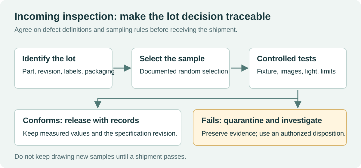
Freeze the acceptance rules before the shipment
The inspection document should identify the module part number and revision, approved drawing, optical requirements, electrical limits, visual-defect criteria, and sampling plan. Make sure it covers the actual supplied configuration, including touch and cover glass if present.
Define bright pixels, dark pixels, subpixel defects, clusters, scratches, contamination, and uniformity separately. Specify the relevant image, viewing conditions, and area boundaries. A defect near critical text may deserve a different disposition from a similar mark outside the active area, but that distinction belongs in the agreement.
Use controlled photographs and retained samples to clarify borderline cases. A golden sample is helpful for comparison; it is not an independent measurement standard and can itself age or change. Keep its identity, storage conditions, and review history.
The industrial TFT purchasing specification should feed this document. If the purchase order asks only for diagonal size and resolution, receiving inspection has little basis for resolving optical or lifecycle disagreements.
Establish the lot and sample correctly
Record supplier lot identifiers, shipment date, quantities, packaging condition, and any mixed revisions before selecting samples. Keep distinct production lots separate unless the agreed plan explicitly defines them as one inspection lot.
Choose samples using the documented random-selection method. Taking the easiest units from the top tray can miss a packaging or production problem concentrated elsewhere. Inspect representative packaging as well as the modules.
NIST’s acceptance-sampling guidance explains that sampling supports a lot acceptance decision, not a precise estimate of the lot’s quality. Its sampling-plan definitions also distinguish producer and consumer risks. An AQL value is not permission to ship that percentage of defective displays, nor a promise that every accepted lot contains fewer defects than that value.
Use the contractually agreed standard, inspection level, defect classes, and switching rules. Do not invent a sample size after seeing the first failure or repeatedly redraw samples until a shipment passes.
Use a fixture that does not create defects
Support the module without twisting the frame or pressing on the active area. Control connector insertion and cable orientation. Follow the module’s ESD handling requirements, power sequence, and backlight drive specification.
Keep a known-good fixture and cable available for confirmation. A damaged fixture connector can make an entire shipment appear intermittent. Record fixture identity and software revision so a later investigation can separate supplier variation from a changed test setup.
Allow the specified optical stabilization period before measurements. Fix ambient lighting, viewing distance, panel angle, and backlight setting. Do not compare one cold module at maximum brightness with another warmed-up module at a different current.
| Inspection stage | What to check | Record to retain |
|---|---|---|
| Identification | Label, revision, quantity, lot, documentation | Label image and receiving record |
| Packaging | Damage, contamination, protection and orientation | Photos before unpacking damaged goods |
| Mechanical | Outline, mounting features, FPC and connector condition | Measured values and drawing revision |
| Unpowered visual | Glass, polarizer, frame, cable and bond edges | Defect location and scale |
| Powered functional | Startup, image stability, pattern sequence, dimming | Fixture version, current and observed faults |
| Optical | Luminance, uniformity, color or viewing behavior as specified | Instrument, geometry, warm-up and results |
| Touch, if supplied | Grid accuracy, edges, release and unintended contact | Controller firmware and test configuration |
Make the pattern sequence purposeful
Each image should expose a different class of problem. Keep automatic brightness, screen savers, and UI overlays disabled during the controlled inspection unless they are part of the test.
| Pattern | Useful observations | Caution |
|---|---|---|
| Black | Bright points, light leakage, unexpected glow | Results depend strongly on ambient light and viewing angle |
| White | Dark points, contamination, gross brightness variation | Check at the specified drive level |
| Red, green, blue | Subpixel defects and channel mapping | A mapping error can originate in the fixture |
| Mid-gray | Mura, pressure artifacts, uneven appearance | Judge under agreed conditions, not arbitrary camera exposure |
| Fine lines and checkerboard | Missing rows or columns, timing and sampling faults | Use a native-resolution pattern |
| Application image | Readability and integration-specific artifacts | Complements, but does not replace, controlled patterns |
Count and classify defects according to the agreed pixel policy. Do not casually combine dark subpixels, full dark pixels, and line defects into one total. For intermittent behavior, save a video and note the time from startup rather than relying on one photograph.
Optical measurements need defined geometry
A phone photograph can document a mark’s location. It cannot reliably certify luminance, color coordinates, or uniformity because exposure, processing, white balance, and lens shading can alter the result.
Use the specified instrument and measurement geometry. For uniformity, record the point locations and formula as well as the value. “Uniformity 80%” is ambiguous without knowing whether it means minimum divided by maximum, which points were measured, and under what drive conditions.
Measure the supplied assembly. A bare LCD and a bonded touch assembly should not be judged against the same luminance number without accounting for the specified optical stack. The industrial display optical-stack tradeoffs explain why the distinction matters.
Incoming checks also differ from environmental qualification. Do not subject every production unit to an improvised thermal or mechanical stress test. Qualification methods, screening methods, and routine receiving checks need separate purposes and acceptance limits. Use the TFT environmental validation plan when a design or process change requires broader evidence.
Quarantine the lot with usable evidence
When a sample fails, identify and segregate the affected lot according to the quality procedure. Preserve labels, packaging, test conditions, photographs, and fixture information. State the violated requirement precisely: “one bright subpixel at coordinate X/Y on black pattern” is more actionable than “screen quality bad.”
Recheck the fixture with a reference unit where appropriate, but retain the original result. A confirmed fixture fault and a confirmed module fault lead to different actions. Engineering concessions, rework, sorting, and supplier returns should have named approval and traceability.
Feed recurring defects into supplier corrective action. Receiving inspection becomes much more useful when it reveals patterns: a repeated cable crease, a particular lot’s color shift, or failures after a revision change. Our LCD failure-mode troubleshooting notes can help frame the technical investigation.
A compact release record
For every inspected lot, retain the specification revision, sample-selection record, results by defect class, measured values, nonconformance references, and release decision. Keep accepted-with-concession units distinguishable from fully conforming stock. When a field issue appears months later, that record is often more valuable than another page of generic checklist ticks.
Sources and photograph
The NIST sources linked above support the sampling concepts. The inspection tables are a practical template; numerical acceptance limits must come from the agreed module specification.
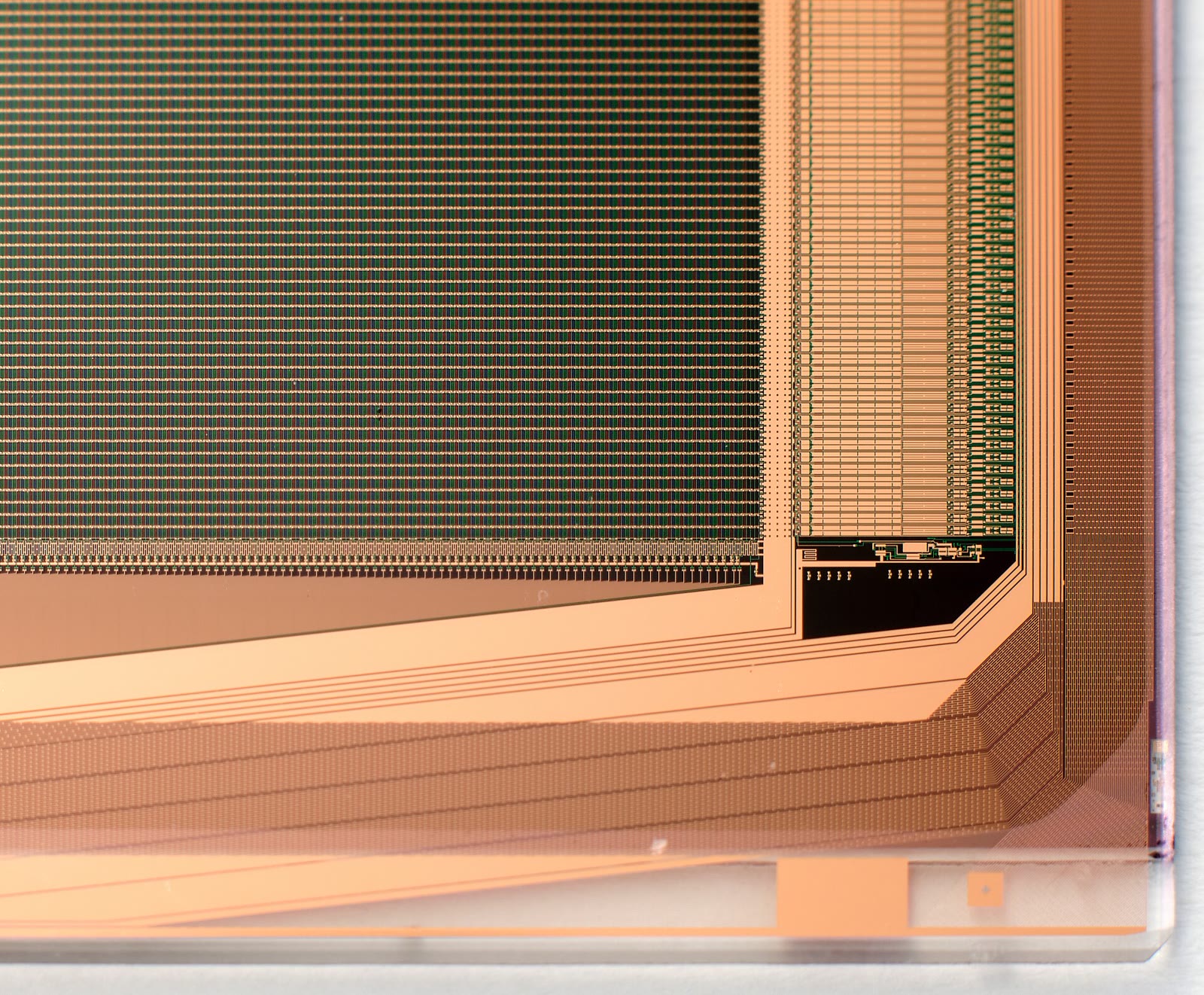
Hero photograph: Jack Whittaker, IPS LCD panel, CC0 1.0. Resized and JPEG-compressed for this page. The inspection-flow diagram is original.