TFT Operating Temperature vs Storage Temperature Explained

A display rated for storage at a low temperature is not automatically rated to start there. Storage and operation describe different conditions, and neither alone establishes how quickly the image becomes readable after a cold soak.
For an industrial product, distinguish environmental survival, powered function, optical performance, and recovery. Then assign the requirement to the complete assembly rather than inheriting one attractive temperature number from the LCD data sheet.
Read the conditions, not just the endpoints
Operating limits describe conditions under which specified operation is supported, subject to the document’s qualifications. Storage limits apply to unpowered storage under stated conditions. Some specifications separate absolute maximum ratings from recommended operating conditions.
An absolute maximum is not a normal design target. A module can also require recovery time before optical measurements after an environmental test. Read those notes before comparing suppliers.
For a concrete example of why footnotes matter, the Kyocera TCG070 module specification distinguishes operating and storage conditions and qualifies optical behavior. Use the applicable revision for the purchased part.
| Rating or condition | What it can establish | What still needs checking |
|---|---|---|
| Operating range | Supported powered conditions | Optical response and exact performance limits |
| Storage range | Unpowered environmental exposure | Startup at the storage endpoint |
| Absolute maximum | Stress boundary | Reliable normal operation |
| Qualification test | Defined exposure and acceptance | Coverage of the actual product mission |
| Recovery condition | Conditions before inspection | Behavior immediately after exposure |
Use the supplier’s definitions where they differ. Do not combine the best endpoint from one document with the best test condition from another revision.
Define the mission in sequences
An outdoor controller may be stored cold, started before sunrise, warmed by its electronics, heated further by sun, and then cooled rapidly after shutdown. Those transitions are more informative than one ambient range.
Write the powered and unpowered phases separately. Include transport, installation, maintenance, and loss of power. A service technician may replace a cold module before it reaches room temperature.
Put those conditions in the industrial TFT environmental specification. They allow a supplier to distinguish a suitable standard module from an application that needs extra thermal control.
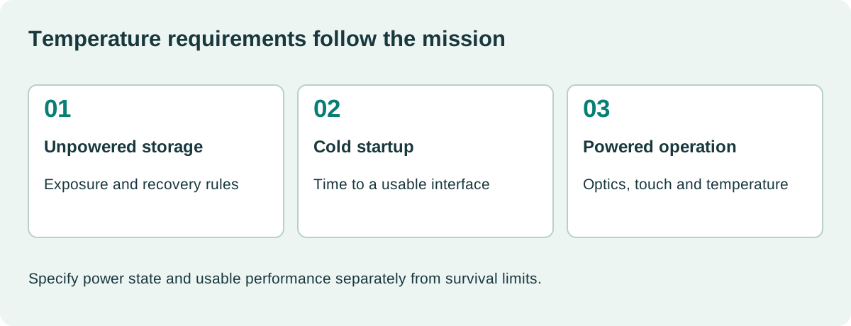
The sequence should identify when the display must be fully usable, when degraded response is acceptable, and when operation is prohibited.
LCD temperature can differ from ambient
The module sits near a backlight, processor, power conversion, and possibly a sealed lens. The hottest location may not be the enclosure’s air sensor.
Measure relevant component and surface temperatures during representative operation. Include maximum backlight drive and the intended host workload. For sunlight exposure, use a setup that represents absorbed external heat as well as ambient air.
Do not subtract a fixed margin from the outside temperature and assume the internal result. Geometry, materials, power, orientation, and ventilation determine the difference.
The wide-temperature machinery display review connects these concerns with installed mounting and operator use.
Cold-start readability deserves its own test
At low temperature, liquid-crystal response may slow. A changing number or moving trace can smear even when a static logo looks acceptable. Test the content that must be interpreted during startup.
Record power-on timing, backlight behavior, contrast, touch response, and time to a defined usable state. Check the host supply too; cold batteries and power components can contribute to symptoms.
A heater can change the startup strategy, but its warm-up time, power budget, sensing, and failure behavior must be defined. Heating one part of the enclosure may leave the lens or LCD edge below the intended temperature.
A successful test at one cold point does not establish every temperature or exposure duration. Use a qualification plan tied to the actual mission.
High-temperature operation is more than a bright image
Backlight life, adhesive behavior, polarizer limits, and electronics ratings can constrain the assembly. Inspect image uniformity and touch behavior while hot, then inspect for persistent changes after recovery.
Kyocera’s industrial TFT information provides access to individual module specifications. Compare those part-level conditions rather than applying the product range’s broadest limit to every option.
If a brightness claim is typical at room temperature, request evidence for the required hot condition. A thermal derating strategy may reduce light output precisely when sunlight makes readability most demanding.
The TFT backlight operating-life review should use the same thermal assumptions.
Humidity and condensation are separate axes
A temperature rating does not establish tolerance to liquid water, condensing humidity, or rapid vapor exposure. A cold product entering warm humid air can collect moisture even if both air temperatures fall within the nominal range.
Compare the coldest surface with the local dew point and examine the powered transition. Display condensation prevention needs a moisture strategy, not only a wider LCD temperature rating.
Do not power a wet assembly simply because its temperature is now acceptable. Follow the product’s validated recovery procedure and inspection criteria.
Include gaskets, cable entries, touch layers, and bonding edges in the environmental review. The LCD’s cell rating does not automatically cover those parts.
Design tests that answer specific questions
| Test | Question |
|---|---|
| Unpowered cold soak and startup | Can the product start and become usable when required? |
| Powered high-temperature dwell | Are function and readability maintained? |
| Unpowered storage exposure | Is the assembly acceptable after the specified recovery? |
| Thermal transition | Does the changing temperature cause resets or mechanical problems? |
| Humid transition | Does moisture obscure the image or affect electronics? |
| Repeated cycles | Does performance drift or damage accumulate? |
Record ramp rates, dwell times, sensor locations, power state, screen content, and acceptance criteria. A chamber setpoint is not proof that the module reached equilibrium.
Distinguish formal qualification from routine production screening. Repeating a severe test on every unit can consume life or introduce damage if it was never designed as a screen.
Tie failures to the assembly revision
If an image fault appears at temperature, preserve the software, cable, mounting load, and backlight setting. Changing several of them before recording the result makes the investigation much harder.
After correction, repeat the original trigger and the relevant recovery sequence. The industrial display validation record should show both functional performance during exposure and condition afterward.
What should purchasing compare?
Compare exact operating requirements, storage conditions, recovery rules, optical limits, and the purchased assembly configuration. Ask for clarification where a data sheet is silent.
The useful conclusion is specific: the assembly starts, remains readable, and recovers under defined conditions. A wider printed range has value only when its definition matches the product’s actual use.
A practical handover detail
Put the required sensor locations into the test drawing before the first chamber run. Record whether a sensor is attached to the LCD frame, cover lens, LED board, or nearby air. Use the attachment method consistently, because a poorly coupled sensor can report a misleading temperature. When comparing suppliers, reproduce power state and soak conditions rather than comparing chamber setpoints alone. Keep the stabilization criterion explicit so a shorter exposure is not accidentally treated as equivalent evidence.
Sources and image credit
Primary technical references are linked beside the relevant claims. Numerical examples are calculations under the stated assumptions. The original diagram explains the design method; neither it nor the photograph represents a qualification test performed by this site.
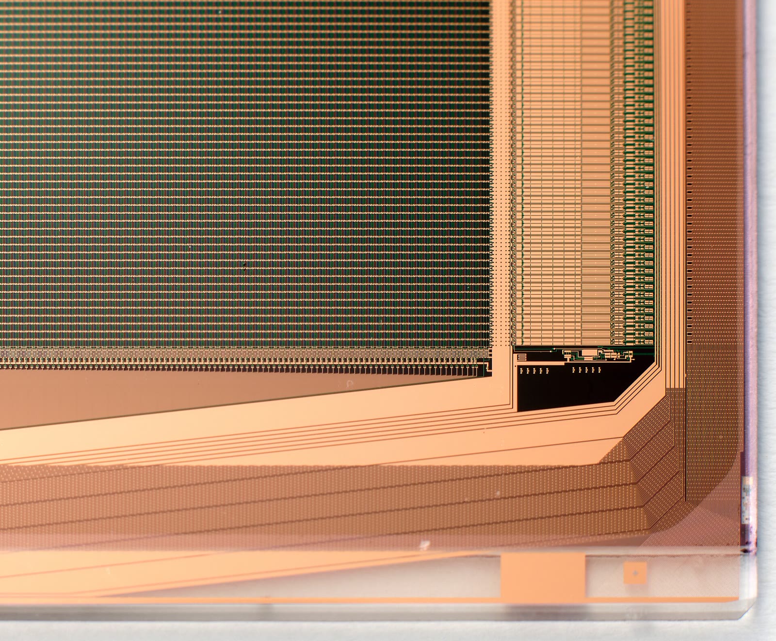
Hero photograph: Tarasna0922, CC BY-SA 4.0. Resized and JPEG-compressed. This adapted photograph remains under the linked ShareAlike license.