TFT Viewing Angles Explained: IPS, TN, and Gray Inversion
A TFT can satisfy its quoted viewing-angle limit and still show an uncomfortable change in gray levels from the operator’s normal position. The apparent contradiction comes from the measurement threshold: a contrast-ratio boundary does not describe every aspect of image quality within that boundary.
For industrial equipment, evaluate readable information over an operator viewing zone. That zone includes mounting height, standing position, shared viewing, and the final cover lens. Panel technology helps select candidates, but the application image decides whether they are suitable.
Read the measurement condition beside the angle
Viewing angles are often specified in several directions at a stated contrast threshold. An angle where contrast remains above a low threshold does not guarantee stable color, gamma, or dark-detail visibility.
Check the direction convention. Up, down, left, and right are relative to the panel’s defined orientation. Rotating the panel changes which characteristic an operator encounters.
| Specification item | What to clarify |
|---|---|
| Contrast threshold | Boundary used to declare the angle |
| Direction convention | Front view and normal panel orientation |
| Typical versus minimum | What is actually guaranteed |
| Image and luminance | Conditions used for the optical measurement |
| Temperature | Whether off-axis behavior was characterized there |
| Complete stack | Whether touch and cover lens are included |
Request additional data or samples if the intended position is close to a boundary. A four-number angle summary is not enough to predict a complex interface.
IPS and TN differ, but neither is a complete requirement
IPS-type panels are commonly selected where several users or broad viewing positions are expected. TN panels can remain useful when viewing geometry is controlled and their optical behavior fits the task.
EIZO’s explanation of LCD viewing behavior discusses changes in halftones and color with viewing direction. Treat that as a technology-level explanation, then verify the chosen industrial module.
Do not assume every IPS panel has identical dark-state behavior or that every TN panel is unusable. The exact cell, polarizers, backlight, and surface treatment matter.
If the product uses a compact fixed panel, a narrow but well-positioned usable zone may be acceptable. A swing-arm HMI shared by two technicians demands a different review.
Gray inversion is more than a dark image
Gray inversion describes a reversal or severe distortion in the intended ordering of gray levels from some directions. It can make a shaded button, selected row, or trend background appear different from the designer’s intent.
Use a gray ramp and the real application to inspect the effect. A panel displaying only saturated color blocks can hide a problem with subtle gray distinctions.
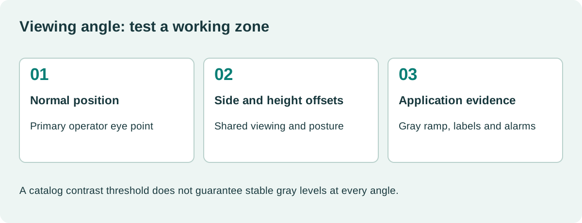
Try the panel above and below the intended eye level, then from both sides. Include the expected tilt range of any adjustable mount. The least favorable combination may be diagonal rather than directly vertical or horizontal.
Our industrial HMI resolution checks should be performed from the same positions. Text size and optical contrast are coupled in the actual reading task.
Build a viewing zone from the installation
Mark the normal eye positions around the equipment and the screen’s tilt. Use a simple sketch with distances and height differences. This is more useful than requesting the largest angle number in a catalog.
For an illustrative geometry, an eye 300 mm above the display center and 600 mm away along the normal direction creates an angle of about 26.6 degrees. That calculation does not establish readability; it identifies a position to test.
A second observer standing to the side introduces another angle. An operator moving between setup and production may need several distinct positions rather than one cone centered on the screen.
Record which positions are required for routine control and which are only convenient for diagnostics. This helps avoid overdesign while preserving important tasks.
Cover lenses can change the apparent result
Reflections, tint, touch layers, and an air gap can reduce usable contrast. A panel evaluated without its lens can therefore pass an angle review that the assembled product fails.
Check optical alignment and whether the bezel blocks the image at oblique angles. Deep protective lips can obscure edge information before the LCD reaches its optical limit.
For relevant assemblies, compare anti-glare and anti-reflective glass and optically bonded TFT stacks using the same viewing zone.
If users wear polarized sunglasses, rotate the eyewear and inspect the full assembly. A screen that is readable with an unfiltered eye can darken strongly through a particular polarizer orientation.
Design the UI to tolerate modest optical variation
Do not rely on a small difference between two gray fills to indicate a critical state. Add text, a symbol, or a clear border. Use color redundantly rather than making one hue the only available meaning.
Keep important text out of regions where reflections dominate at the normal position. If a slight mount adjustment resolves the issue, include that geometry in installation instructions rather than leaving it to field improvisation.
| Test image | What it exposes |
|---|---|
| Gray ramp | Lost steps, inversion and gamma changes |
| Dark background with small text | Low-level visibility |
| Selected and unselected controls | State ambiguity |
| Colored trends with labels | Channel distinction |
| Alarm overlay | Critical information across the zone |
| Edge labels | Bezel obstruction and oblique readability |
Aesthetic uniformity across every possible angle may be unnecessary. Clear and consistent interpretation across required positions is the practical target.
Qualify the mount as well as the LCD
The final test should include enclosure tilt, cover glass, screen brightness, room lighting or sunlight, and representative operators. Fix automatic brightness where necessary for repeatable optical comparison.
Photograph the setup and record camera settings, but avoid using automatically processed photographs as the only acceptance evidence. Human task evaluation and instrument measurements answer different questions.
Keep the industrial display validation record tied to the final mount and module revision. A replacement with the same diagonal and nominal angle can behave differently in the installed orientation.
What should replace “wide viewing angle required”?
State the operator positions, important tasks, optical stack, light conditions, and pass criteria. Add minimum optical specifications where useful, but retain the application test.
That makes the requirement maintainable. If a supplier proposes another IPS panel or a differently oriented module, the team can evaluate it against the same viewing zone instead of debating labels or assuming a larger catalog number must be better.
A practical handover detail
An angle review should include a disagreement case: two people looking at the same selected row or alarm from different positions. Ask whether they identify the same state without being prompted. A broad gray shift may be cosmetically acceptable while a reversal between selected and unselected fills is not. Preserve that test image as part of the acceptance set. It turns a subjective complaint about color into a repeatable question about the meaning of the interface.
Sources and image credit
Primary technical references are linked beside the relevant claims. Numerical examples are calculations under the stated assumptions. The original diagram explains the design method; neither it nor the photograph represents a qualification test performed by this site.
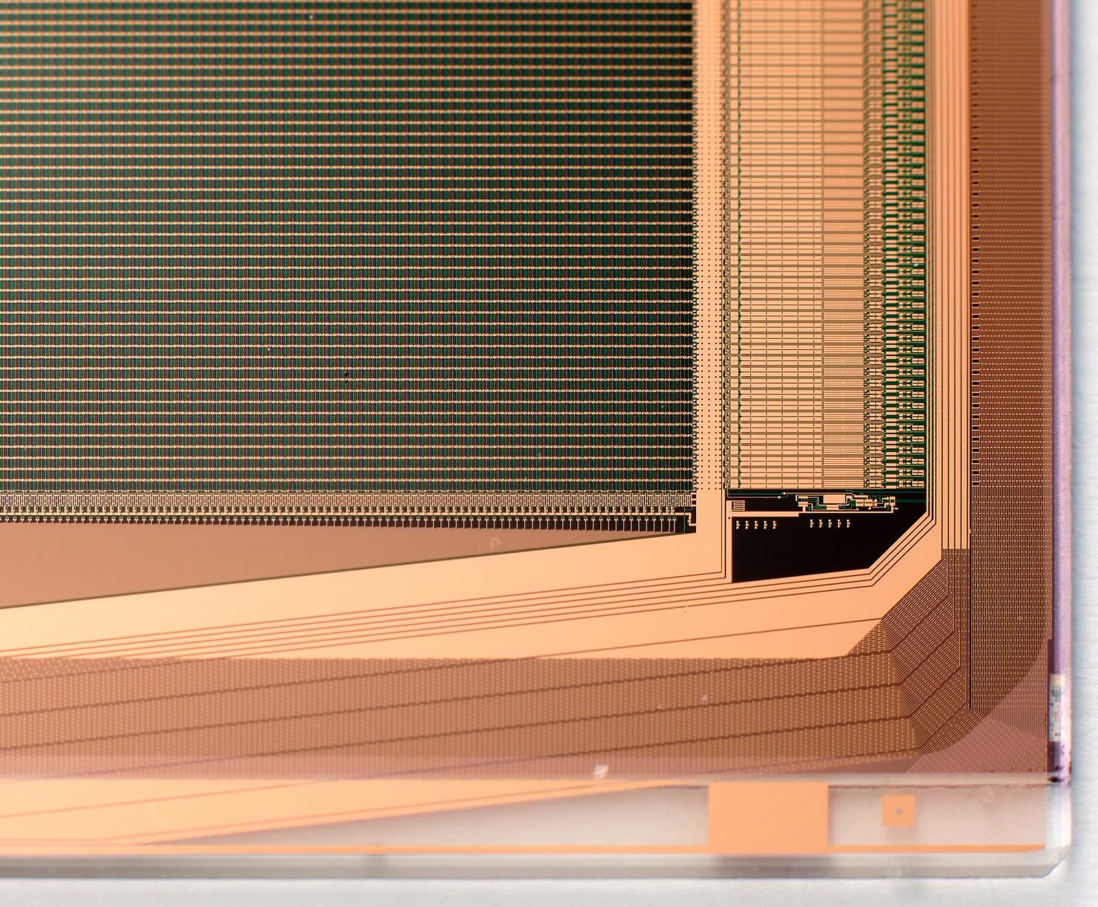
Hero photograph: Jack Whittaker, CC0 1.0. Resized and JPEG-compressed.