Rugged TFT Displays for Tractors and Agricultural Machinery
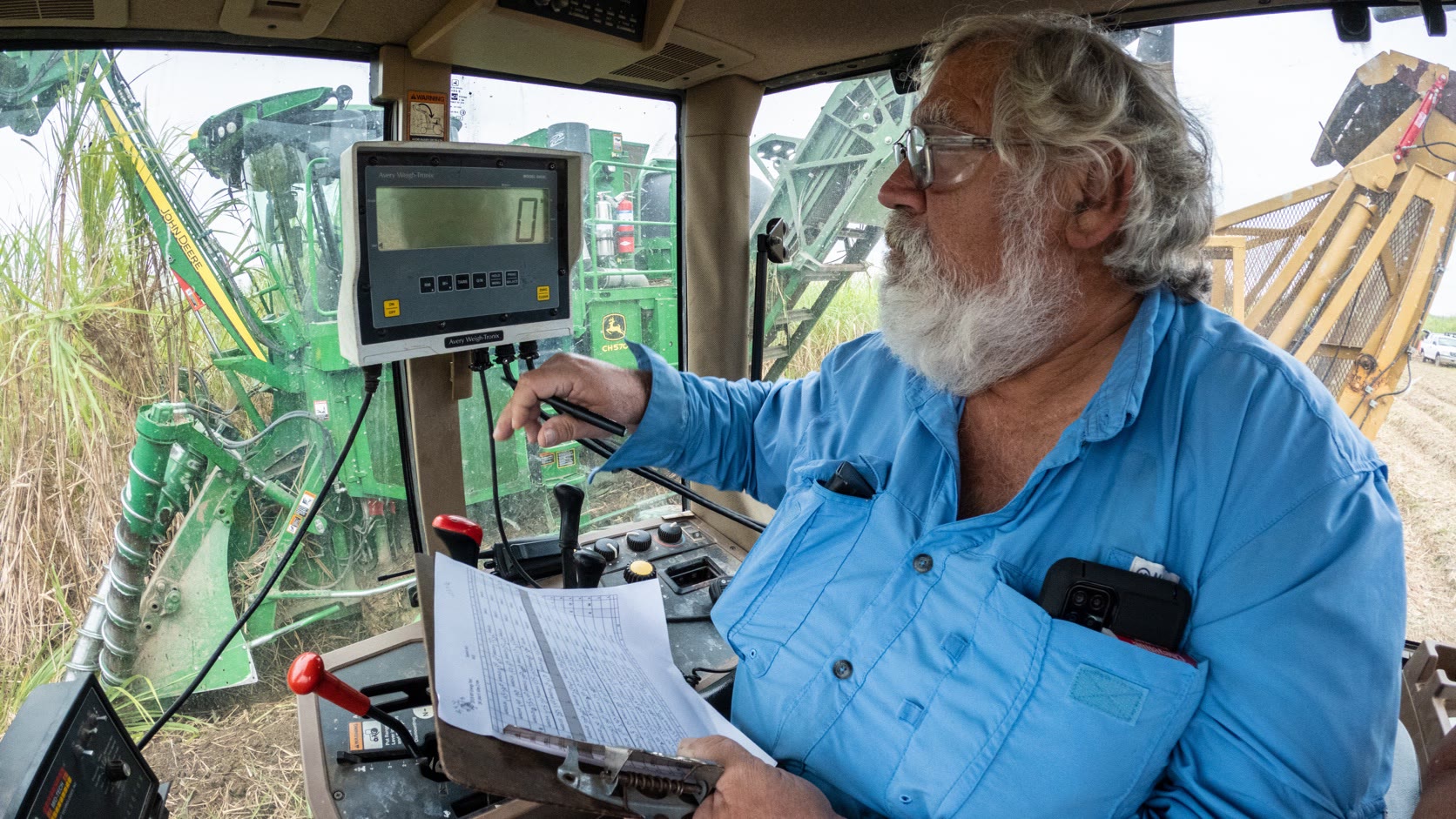
A tractor display has to be readable while the cab is vibrating, sunlight is moving across the glass, and the operator is watching an implement rather than staring at the screen. It may show vehicle status, guidance, camera video, job data, application rate, hydraulic functions, and alarms. The design problem is not how much information fits. It is how much information can be understood at a glance.
Agricultural machinery also has a long and messy service life. Displays see dust, fertilizer residue, pressure washing, cold starts, jump-start events, and accessories added years after the original electrical design. A module chosen from a desk specification rarely covers all of that without system-level work.
Separate the dashboard from the implement terminal
A vehicle cluster and an implement terminal have different priorities. The cluster emphasizes speed, engine state, warnings, and essential vehicle information. An implement terminal may handle seeding rate, section control, boom status, guidance, maps, cameras, and task records. Combining everything into one display can reduce hardware, but it also creates a single point of failure and a crowded UI.
| Display role | Typical content | Design priority |
|---|---|---|
| Instrument cluster | Speed, RPM, fuel, temperatures, warnings | Fast startup and glance readability |
| Implement terminal | Rates, sections, depth, alarms, setup | Flexible layouts and ISOBUS compatibility |
| Guidance display | Map, path, coverage, steering status | Sunlight readability and graphics performance |
| Camera monitor | Rear or implement video | Low latency and viewing angle |
| Service display | Diagnostics, calibration, I/O | Detail, logging, and connector access |
If one screen carries several roles, define a degraded mode. What remains visible after a camera fault, a network error, or a failed application? Vehicle-critical warnings should not disappear behind a third-party implement page.
Sunlight inside a cab is still sunlight
A cab roof does not make a display indoor equipment. Light enters through several windows and reflects from dust, clothing, plastic trim, and the operator. At some sun angles, the front glass behaves like a mirror.
High brightness helps, but the full optical stack decides readability. A practical design combines sufficient luminance, low internal reflection, an appropriate anti-glare surface, wide viewing angle, and a UI with strong contrast. Optical bonding is often valuable because it reduces internal reflections and strengthens the display stack. It also complicates repair, so the service model matters.
Automatic brightness should respond smoothly. A sensor mounted where the operator’s hand or cab pillar shades it may drive the backlight in the wrong direction. Keep a manual override, define day and night limits, and test sunset and headland-turn conditions. The principles in our high-brightness industrial TFT guide apply directly to cab displays.
Polarizers can interact with sunglasses. Rotate the final display through likely viewing angles while wearing the eyewear used by operators. A screen that blacks out in portrait orientation is not fixed by increasing brightness.
Vibration and mechanical mounting
Continuous low-frequency cab motion and higher-frequency engine or implement vibration act on the display, PCB, connector, and mount. A ball mount that is convenient on a stationary prototype may shake enough to make text unreadable in the field.
Support the display close to its center of mass and check the mount’s resonances. Use locking connectors and strain relief. The cable should not carry the weight of an unsupported service loop. Inside the housing, avoid rigidly clamping the LCD so tightly that enclosure flex transfers into the glass.
Drop and impact requirements differ for fixed and removable terminals. If the display can be carried out of the cab, test the likely corner drops with the cable disconnected and connected as appropriate. A robust cover lens does not protect a weak connector or mounting boss.
Touch with gloves, dust, and moisture
PCAP supports a sealed front and modern gestures, but it needs application-specific tuning. Operators may use leather work gloves, nitrile gloves, bare fingers, or a stylus. Dust and water droplets change the touch signal. Test the named glove types with the final cover glass and bezel.
Large targets and restrained interaction help on a moving machine. Avoid small drag handles for important settings. A physical rotary controller or a few programmable keys can make common actions easier without looking at the screen. Camera selection, home, acknowledge, and zoom are candidates, depending on the machine.
If the terminal is used outside the cab, rain rejection matters. The outdoor touch guide covers wet-touch tradeoffs and why “waterproof touchscreen” is not a complete requirement.
CAN, J1939, and ISOBUS
Agricultural displays frequently connect to CAN-based networks. SAE J1939 is widely used for heavy-duty vehicle communication, while ISO 11783—commonly associated with ISOBUS—standardizes communication among tractors, implements, controllers, sensors, and display units.
The ISO 11783-1 overview describes the overall mobile data communication standard. Its purpose includes standardized transfer among sensors, actuators, control elements, storage, and display units. The current SAE J1939 top-level document defines the network’s document structure and terms.
For the display engineer, protocol support is only one part of the job. Also define:
- boot time before network data is shown;
- handling of missing, stale, or out-of-range values;
- address conflicts and device replacement;
- bus-off recovery and diagnostic logging;
- firmware compatibility with existing implements;
- connector pinout, termination, shielding, and ground strategy.
Our CAN and RS485 industrial terminal guide provides a practical starting checklist for wiring and diagnostics.
Power transients and thermal design
Vehicle power is not a clean laboratory supply. Cranking, load changes, reverse connection, alternator behavior, jump starting, and inductive loads can disturb the HMI input. The power front end should be designed and tested for the target machine architecture. Do not assume the display module’s nominal voltage rating covers the vehicle environment.
Solar heating can raise the display surface and enclosure above ambient temperature. Measure the worst mounting position in a parked cab. High backlight current adds heat, so brightness control should respond to both ambient light and internal temperature where necessary.
At low temperature, LCD response slows. The display may still meet its static optical specification while maps and camera images smear during movement. Test dynamic content after a full cold soak, not only a stationary menu.
Field-oriented validation
| Test condition | What to verify |
|---|---|
| Midday sun from several angles | Critical values, warnings, and map details remain readable |
| Night operation | Dims low enough without losing alarm distinction |
| Rough field and road transport | Text remains readable; mount and connectors stay secure |
| Cold crank | HMI resets predictably and does not corrupt settings |
| Hot parked cab | No LCD darkening, touch drift, or uncontrolled shutdown |
| Gloves, dust, and wet glass | Intended input works without false commands |
| Implement connect/disconnect | Network state and faults are explained clearly |
| Pressure wash or cleaning | Seals, coatings, connectors, and vents remain sound |
Run tests on a representative tractor and implement. A shaker table and chamber are valuable, but they cannot reproduce every mounting resonance, sun angle, or wiring change. Record field observations with ambient conditions and software version so a symptom can be reproduced later.
Questions engineers ask early
Is a high-nit panel enough for a tractor cab?
No. Cab readability depends on brightness, internal reflection, cover-glass treatment, polarizer orientation, viewing angle, UI contrast, and thermal behavior under solar load. Test the complete terminal at several sun angles.
What is the difference between J1939 and ISOBUS for the display?
Both use CAN-based communication in relevant applications, but their message sets and system roles differ. SAE J1939 is widely used for heavy-duty vehicle networks; ISO 11783 defines the agricultural communication system commonly associated with ISOBUS and implement interoperability.
Bottom line
A good agricultural display keeps the operator’s attention on the machine and field. It starts quickly, remains readable from dawn to full sun, survives vibration, explains network faults, and works with real gloves. Design the optical, mechanical, electrical, and communication system together; the TFT panel alone cannot make a terminal rugged.
Engineering references and image credit
- ISO 11783-1:2017 — Mobile data communication for agricultural machinery
- SAE J1939_202603 — Heavy-duty vehicle network top-level document
- IEC 60529: Degrees of protection provided by enclosures
Hero photograph: Lance Cheung / USDA, via Wikimedia Commons. Work of the U.S. Department of Agriculture, public domain. Cropped and resized for this page. The photograph is illustrative; no equipment manufacturer endorsement is implied.

.jpg)