TFT HMIs for Water and Wastewater Treatment Systems
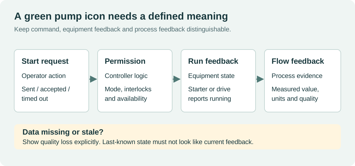
A pump symbol turns green when the operator presses Start. Does that mean the command was sent, the motor starter energized, the drive reported running, or flow actually appeared? Those are different states. A water treatment HMI should make the distinction obvious.
Selecting a water treatment HMI display is partly an optical and environmental task, but the more consequential work is deciding what the screen can truthfully say about the process. Clear feedback, visible data quality, and predictable operation during communication faults belong in the requirements before panel size and styling.
Build the page around operating decisions
Begin with the operator’s routine questions. Which unit is available? What is running? Is the level rising? Why did the duty pump fail to start? Who currently has control? A process drawing is useful only if it helps answer those questions quickly.
Use consistent navigation between the overview, equipment detail, trends, and alarms. Keep the current control mode visible when a dialog opens. Local, remote, manual, and automatic are not interchangeable labels; define their meaning with the control-system designer and use the same terms throughout the site.
The ISA101 HMI committee’s scope covers navigation, graphics, dynamic elements, alarms, and related interface conventions. That is a useful framework for developing a plant-specific HMI philosophy, rather than designing each page independently.
Give every displayed value a quality state
An unchanged number may be stable, frozen, invalid, or disconnected. Do not leave those interpretations to the operator. Define how the HMI presents stale data, out-of-range measurements, maintenance substitution, and communication failure.
| Displayed item | Meaning to preserve | Misleading shortcut to avoid |
|---|---|---|
| Tank level | Value, units, validity, update state | Keeping the last number without a stale indication |
| Pump state | Command, run feedback, fault and availability | Coloring the pump from the command bit alone |
| Valve position | Actual feedback or explicitly labeled command | Showing a commanded position as a measured position |
| Flow trend | Time base, units, gaps and quality | Drawing a continuous line through missing samples |
| Control mode | Authority and permitted actions | Hiding local/remote mode inside a settings page |
| Alarm | Condition, priority, acknowledgment and return state | Treating acknowledgment as fault clearance |
Set freshness thresholds from the process and communication design. A slowly changing reservoir level and a rapidly changing local control signal do not need identical thresholds. Record the chosen values and verify that their behavior is useful during real commissioning scenarios.
Use color with text or symbols. A red or green icon alone can be ambiguous, especially under glare or for a user with limited color discrimination. Keep normal-state graphics restrained enough that an abnormal condition stands out without relying on animation everywhere.
Keep control authority in the right place
The HMI should show whether an action is permitted and explain why it is unavailable. The control system must enforce the actual interlocks, permissions, and process protections. A disabled touchscreen button is not, by itself, an interlock implementation.
Define command behavior across a dropped connection. An operator should not have to guess whether a request was accepted. Use the control protocol’s supported acknowledgment and state model, and show a timeout or failure explicitly. Avoid automatically replaying an old command after reconnection unless the control design specifically requires and validates that behavior.
These concerns apply whether the panel connects over industrial Ethernet or a serial link. For smaller installations, RS485 industrial HMI integration also requires disciplined handling of retries, device addressing, and loss of communication.
Choose the screen for the installation position
A sheltered indoor process room has different needs from an outdoor lift-station cabinet. Survey the mounting height, approach direction, sunlight, task distance, and whether operators work with gloves or wet hands.
For outdoor installations, evaluate sunlight-readable TFT assemblies through the finished cover glass. A high nominal panel brightness can be undermined by reflected sky or a poor viewing angle. Check the screen with the cabinet door in its normal operating position and with the sun at an unfavorable angle.
Touch behavior should be tested with the actual gloves and water exposure. If the interface supports wet operation, verify both intended touches and rejection of water-induced contacts. Keep a practical method for cleaning or drying the front without triggering commands. Our wet and gloved touchscreen design notes cover those interactions in more detail.
Humidity and chemicals affect the whole assembly
Review the enclosure, seals, cable entries, exposed metals, adhesive edges, and front-surface coatings together. The environment can include persistent humidity, cleaning agents, and site-specific corrosive exposure. Do not assume one stainless-steel bezel or an IP rating resolves every material-compatibility question.
If condensation is plausible, log both internal humidity and the temperature of the cover lens or other cold surfaces. Sealed HMI condensation control requires a moisture strategy as well as a liquid-water seal. Cabinet heating, ventilation, or desiccants should be selected from the measured conditions and maintenance plan.
At sites with a classified hazardous location, the complete equipment and installation need the applicable assessment. A rugged display description does not establish suitability for that location. Keep that decision with the project’s electrical and process safety requirements.
Include the panel in the OT maintenance plan
Record the HMI hardware, operating system or firmware, application version, network role, and recovery procedure. Control access to engineering functions and remote maintenance. Keep backups that can actually restore a replacement panel, including communication settings and compatible software versions.
NIST SP 800-82 Rev. 3 addresses operational-technology security while accounting for performance, reliability, and safety requirements. Use it to inform the site’s access and maintenance approach. It does not make a particular TFT module or HMI product secure by association.
Plan replacement work before a failure. A maintenance technician needs the correct panel image, cables, mounting details, and a procedure for confirming that process indications and controls are mapped correctly after installation.
Commission with failures as well as normal operation
| Commissioning scenario | Expected evidence |
|---|---|
| Start request without run feedback | Command state and failed-start condition remain distinguishable |
| Communication cable disconnected | Stale values are marked and inappropriate commands are unavailable |
| Local selector takes control | HMI clearly shows changed authority and action limits |
| Sensor maintenance or substitution | Substituted data cannot be mistaken for a live measurement |
| Alarm acknowledged while fault persists | The continuing condition stays visible |
| HMI restart during plant operation | Correct state is recovered without unintended command replay |
| Trend data missing during outage | The gap is visible and timestamps remain interpretable |
| Wet front and intended gloves | Reliable intended operation without spurious commands |
Perform disruptive checks in a simulator, test environment, or approved commissioning window. Agree on acceptance criteria with operations and the control-system team. Save screenshots and logs showing both the initiating event and the recovery.
The best handover includes a short explanation of each displayed state and what the operator should do when data quality is lost. That makes the screen useful when the process is least routine, which is when its clarity matters most.
Sources and photograph
ISA and NIST references are linked beside their scope. The state model and commissioning table are design guidance, not operating instructions for the photographed facility.
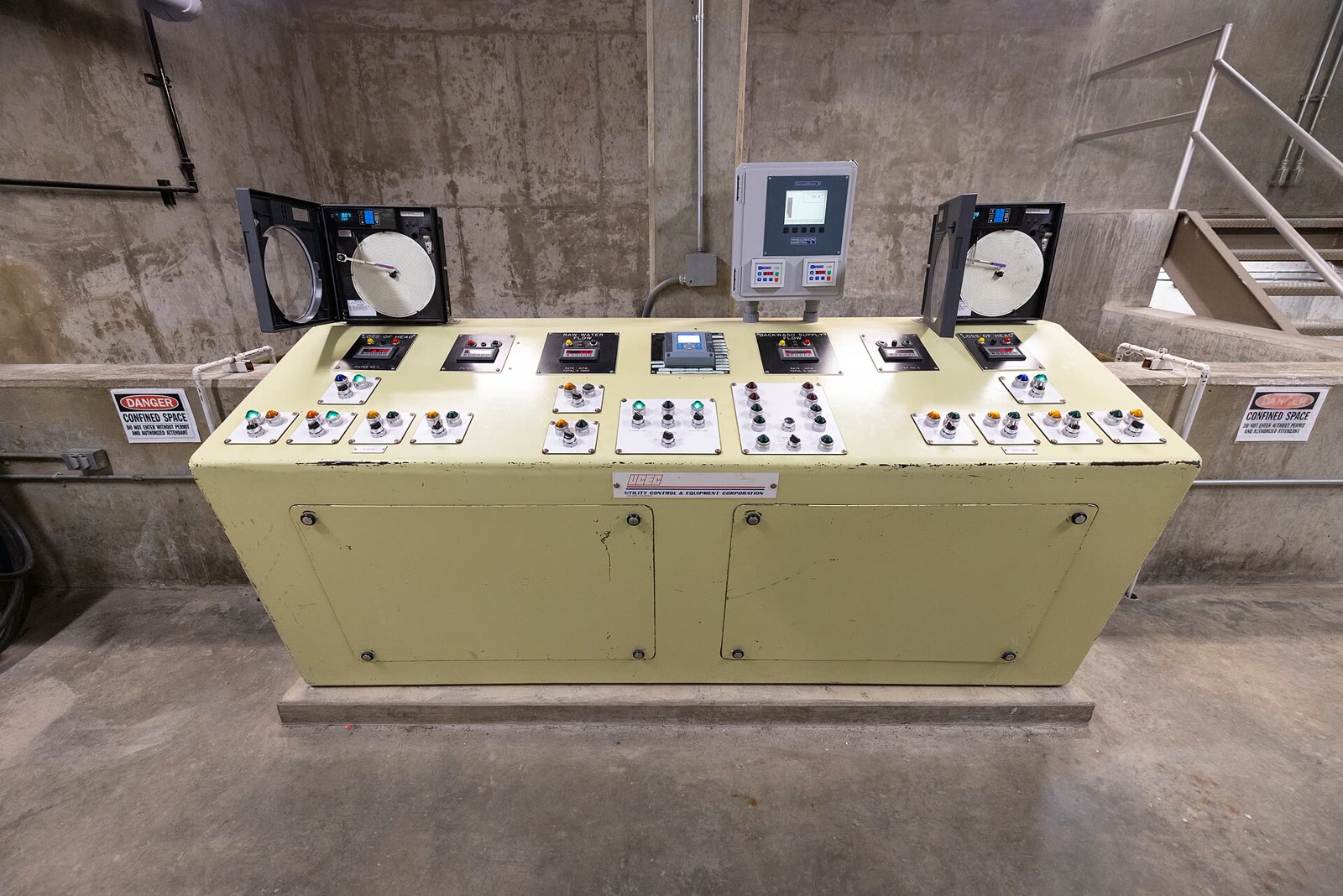
Hero photograph: NPS / Jacob W. Frank, Grant Village water treatment plant control panel. U.S. National Park Service photograph, public domain in the United States. Resized and JPEG-compressed. The data-quality illustration is original.

.jpg)