Rugged HMI Displays for Wind Turbine Systems
A wind turbine HMI is usually a service interface, not the main operating console. Normal operation is supervised through SCADA, while a local display helps technicians commission equipment, check sensors, jog permitted functions, review alarms, and isolate a fault. That local role is important because the technician may be working in a nacelle, tower base, converter cabinet, or outdoor substation where access is difficult and conditions are inconsistent.
The display therefore needs more than a wide temperature label. It must start after a cold soak, remain readable near an open tower door, tolerate condensation, communicate clearly when remote data is unavailable, and stay supportable across a long asset life.
Decide where the HMI will live
“Wind turbine display” can refer to several different installations:
| Location | Main environmental concern | Typical HMI use |
|---|---|---|
| Tower base cabinet | Condensation, dust, limited heating | Status, reset, commissioning, network checks |
| Nacelle cabinet | Vibration, heat, oil mist, difficult access | Drive, pitch, yaw, lubrication, sensor diagnostics |
| Outdoor substation | Sun, rain, temperature extremes | Switchgear and plant status |
| Service laptop/dock | Portability and connector wear | Detailed diagnostics and firmware work |
| Control room | Information density and alarm handling | Fleet or plant supervision |
These should not automatically share one hardware specification. A 7-inch panel inside a heated tower base can be perfectly adequate, while an exposed outdoor panel may need high brightness, optical bonding, a sealed front, and solar-load testing. Define the location before selecting the TFT.
Temperature range is only the first filter
Wide-temperature TFT modules are often rated around -20°C to +70°C or -30°C to +80°C. Those numbers help filter candidates, but startup and visual behavior matter more than the endpoints alone. At low temperature, liquid crystal response slows. At high temperature, backlight life falls and some panels can show temporary contrast changes.
Test cold start, not just cold operation. A local service HMI may be switched on only when a technician enters the tower. It should boot, illuminate, and present critical state within an agreed time after a cold soak. If the display remains sluggish for several minutes, document whether that is acceptable for the service procedure.
High-brightness backlights add heat inside sealed cabinets. Use temperature-based derating and automatic dimming where appropriate. Our backlight lifetime and dimming guide explains why running at maximum current continuously is rarely the best lifecycle choice.
Condensation deserves its own test
Tower interiors can move through temperature and humidity changes quickly. Warm moist air meeting a cold cover lens can create surface fog; an air gap inside the display stack can create internal condensation. A panel may pass a steady-state humidity test and still fog during a realistic transition.
Optical bonding removes the internal air gap and can improve mechanical strength, but it does not eliminate condensation elsewhere in the enclosure. Cabinet heating, ventilation, drainage, gasket design, and pressure equalization remain system issues. If the HMI is mounted in an outdoor door, review the complete stack described in our wide-temperature heavy equipment guide.
Run temperature-humidity cycling with the assembled panel. Look for fogging, touch drift, corrosion at connectors, coating changes, and trapped moisture at the cover-glass edge. Recheck after aging; a new gasket and a gasket after compression set can behave differently.
Readability in service conditions
The operator may read a tower-base panel in dim light, then open a door and flood the screen with daylight. Automatic brightness control is useful if it behaves predictably. Avoid aggressive dimming that makes an alarm appear to disappear when the ambient sensor is shaded by a technician.
For direct outdoor viewing, use the same stack-level approach as a sunlight-readable outdoor display: brightness, anti-reflection, cover glass, bonding, thermal design, and UI contrast work together. Nits alone are not a complete specification.
Nacelle service can also happen in low light. The backlight should dim far enough for comfortable close viewing without losing color distinction. Do not communicate safety-relevant state by color alone. Pair color with text, shape, or icon and keep the active machine mode visible on every service page.
Touch and physical controls
PCAP touch supports a sealed glass front, but gloves, water, oil residue, and grounded metal require tuning. Service gloves should be named in the test plan. “Works with gloves” is not specific enough.
Local movement commands deserve careful treatment. Pitch, yaw, and other controlled movements are not ordinary menu actions. The HMI should operate within the turbine’s safety architecture and service procedures, with required enable devices, modes, interlocks, and physical emergency controls. A drawn touchscreen button is not a substitute for the required safety function.
For frequently used local actions, physical controls may be easier to operate while wearing gloves or maintaining a stable stance. Touch remains valuable for alarm history, trends, parameter review, and guided checks.
Communications and loss of data
Wind plants combine turbine controllers, plant controllers, SCADA, protection equipment, and condition monitoring. IEC 61400-25 defines models and communication principles for wind power plant monitoring and control; the IEC 61400-25-1 overview describes the client-server framework and the separation of information models, exchange models, and protocol mapping.
The local HMI should distinguish at least three conditions:
- the measured value is valid and current;
- the value is stale because communication has stopped;
- the value is unavailable or invalid at the source.
Displaying the last number without its quality or timestamp can mislead a technician. Use a clear stale-data treatment and preserve local alarm context when a network link fails. If the HMI can issue commands, define what happens to an unacknowledged or delayed command after reconnection.
Vibration, connectors, and maintainability
The display module itself may survive vibration while its connector or cable does not. Support the cable close to the connector, protect it from sharp cabinet edges, and avoid an unsupported loop that moves continuously. Locking connectors are preferable where access is difficult.
Use even frame support and controlled fastener torque. A twisted bezel can create pressure marks and false touch behavior. Check the screen while the turbine or a representative shaker profile is operating, not only afterward.
Service life is a procurement issue as much as a reliability issue. Wind assets can operate far longer than a consumer display family remains available. Record the panel timing, mechanical envelope, backlight interface, touch protocol, optical stack, and approved substitutes. Plan how software will handle a replacement resolution before the first end-of-life notice arrives.
Qualification checklist
| Test | Practical acceptance point |
|---|---|
| Cold soak and start | Boots and becomes usable within the service requirement |
| Hot operation | No thermal shutdown, excessive dimming, or touch drift |
| Temperature/humidity transition | No internal fogging or persistent condensation |
| Vibration | No image interruption, connector movement, or false touch |
| Glove/wet touch | Intended input works; water does not create unsafe commands |
| Day/night readability | Alarms and machine state remain clear across the dimming range |
| Network loss | Stale and invalid values are unmistakable |
| Power cycling | Restart state and local/remote mode are predictable |
Use the production controller, cable lengths, power supply, enclosure, and grounding. A display tested alone cannot reveal every system-level failure. Adapt the industrial TFT validation checklist to the target turbine location and maintenance procedure.
Questions engineers ask early
What is a local wind turbine HMI used for?
It is mainly a commissioning and service interface. Technicians use it to inspect state, alarms, sensors, communications, and permitted local functions while normal fleet or plant supervision remains in SCADA.
Does optical bonding prevent condensation?
It removes the internal air gap and can prevent fogging in that layer, but it does not control moisture inside the cabinet. Heating, sealing, ventilation, drainage, and humidity transitions still require system-level design and testing.
Bottom line
A rugged wind turbine HMI should help a technician understand plant state without adding doubt about data quality, local mode, or command status. Specify it by location, test cold start and condensation transitions, and keep serviceability in the design. The display may be used only occasionally, but when it is needed, the turbine is often already offline.
Engineering references and image credit
- IEC 61400-25-1: Communications for monitoring and control of wind power plants
- IEC 60529: Degrees of protection provided by enclosures
- ISA-101 series for HMI lifecycle and design
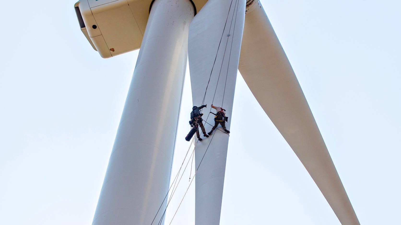
Hero photograph: Werner Slocum / NREL, via the U.S. Department of Energy and Wikimedia Commons. U.S. federal government work, public domain. Cropped and resized for this page. The photograph is illustrative; no organization endorsement is implied.

.jpg)